
Owner manual


8 Brocade 7800 Extension Switch Hardware Reference Manual
53-1001350-04
Installing and configuring the Brocade 7800
2
• Ensure that airflow and temperature requirements are met on an ongoing basis,
particularly if the Brocade 7800 is installed in a closed or multirack assembly.
• Verify that the additional weight of the Brocade 7800 does not exceed the cabinet’s weight
limits or unbalance the cabinet in any way.
• Secure the cabinet to ensure stability in case of unexpected movement.
For additional installation, electrical, environmental, and other considerations, see the
Brocade Safety Guide.
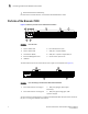
Items included with the Brocade 7800 Extension Switch
The following items are included with the standard shipment of the Brocade 7800:
• The Brocade 7800 Extension Switch, containing two combined power supply/fan
assembly FRUs
• The following rack mount kits are optionally available:
• Fixed rack mount kit, with installation instructions
• Slide rack mount kit, with installation instructions
• Mid-mount kit, with installation instructions
• One accessory kit, containing the following items:
• QuickStart Guide
• Brocade Documentation CD
• SFP transceivers for Fibre Channel ports:
• Base model - 4 SWL optical
• Upgrade model - 16 SWL optical
• SFP transceivers for the GbE ports - upgrade model - 4 copper or 6 SWL optical
(optical SFPs must be 4 Gbps, not 8 Gbps)
• Rubber mounting feet (to be used when setting up the Extension Switch as a
standalone unit)
• Two grounded 6-ft (approximately 1.83 m) power cords:
• Power plug type is NEMA5-15
• Power plug current/voltage rating: 15A/125V
• Cordage type: SVT
• Current rating/wire gauge: 10A/ 18AWG
• Connector at system end of cordset: IEC 60320/ C13
• Two power cord retainers
• One RJ-45 serial cable, 10-ft (approximately 3 m) long. The Extension Switch uses an
RJ-45 connector for the console port. An RJ-45 to DB9 adaptor is also provided with
the Brocade 7800.