® Brocade Mobility RFS4000 Controller Installation Guide Supporting software release 4.3.0.
Copyright © 2011 Brocade Communications Systems, Inc. All Rights Reserved. Brocade, the B-wing symbol, BigIron, DCX, Fabric OS, FastIron, IronPoint, IronShield, IronView, IronWare, JetCore, NetIron, SecureIron, ServerIron, StorageX, and TurboIron are registered trademarks, and DCFM, Extraordinary Networks, and SAN Health are trademarks of Brocade Communications Systems, Inc., in the United States and/or in other countries.
1 Introduction 1 Package contents . . . . . . . . . . . . . . . . . . . . . . . . . . . . . . . . . . . . . . . . . . . . . . . . . . . . .2 Document conventions . . . . . . . . . . . . . . . . . . . . . . . . . . . . . . . . . . . . . . . . . . . . . . . .2 Warnings . . . . . . . . . . . . . . . . . . . . . . . . . . . . . . . . . . . . . . . . . . . . . . . . . . . . . . . . . . . .3 Site preparation . . . . . . . . . . . . . . . . . . . . . . . . . . . . . . . . . . . . . . . . . . . . . . . . . . . .
Verifying the installation . . . . . . . . . . . . . . . . . . . . . . . . . . . . . . . . . . . . . . . . . . . . . . . 24 5 Regulatory Information 25 Power supply . . . . . . . . . . . . . . . . . . . . . . . . . . . . . . . . . . . . . . . . . . . . . . . . . . . . . . . . 25 Country selection . . . . . . . . . . . . . . . . . . . . . . . . . . . . . . . . . . . . . . . . . . . . . . . . . . . . . 26 Laser devices - Gigabit Ethernet SFP option . . . . . . . . . . . . . . . . . . . . . . . . . . . . .
About This Document In this chapter • Audience • Supported hardware and software • Document conventions • Contacting Brocade • Warranty coverage v v vi vi vii Audience This document is designed for system administrators with a working knowledge of Layer 2 and Layer 3 switching and routing. If you are using a Brocade Layer 3 switch, you should be familiar with the following protocols if applicable to your network – IP, RIP, OSPF, BGP, ISIS, IGMP, PIM, DVMRP, and VRRP.
Document conventions This section describes text formatting conventions and important notice formats used in this document. Notes, cautions, and warnings The following notices and statements are used in this manual. They are listed below in order of increasing severity of potential hazards. NOTE A note provides a tip, guidance or advice, emphasizes important information, or provides a reference to related information.
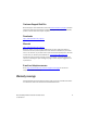
Customer Support Web Site Brocade Support Central Web site, located at www.brocade.com/support provides information and online assistance including developer tools, software downloads, product manuals and online repair requests. Downloads http://www.brocade.com/support/ Manuals http://www.brocade.com/support/ Because quality is our first concern at Brocade, we have made every effort to ensure the accuracy and completeness of this document.
viii Brocade Mobility RFS4000 Controller Installation Guide 53-1001933-02
Chapter 1 Introduction In this chapter • Package contents • Document conventions • Warnings • Site preparation 2 2 3 3 The Brocade Mobility RFS4000 Controller is a member of Brocade’s Mobility wireless controller family. The Brocade Mobility RFS4000 Controller provides centralized Wireless LAN (WLAN) configuration and management by coalescing a network “intelligence” previously spread across physically distributed access points.
1 Package contents Package contents Inspect the package contents and report any missing or damaged items to your sales representative.
Warnings 1 Warnings • Read all installation instructions and site survey reports, and verify correct equipment installation before connecting the system to its power source. • Remove jewelry and watches before installing this equipment. • Install the equipment in a rack or on a desktop with adequate dimensions and weight allowances. • • • • • Verify the unit is grounded before connecting it to the power source. Verify any device connected to this unit is properly wired and grounded.
1 Site preparation • Ensure adequate, dust-free ventilation to all installed equipment. • Identify and prepare Ethernet and console port connections. • Verify that cable lengths are within the maximum allowable distances for optimal signal transmission. • Verify that the Brocade Mobility RFS4000 Controller is powered through an Uninterruptible Power Supply (UPS).
Chapter 2 Specifications In this chapter • Physical specifications • Power cord specifications 5 5 Physical specifications Width 304.8mm (12.0in) Height 44.45mm (1.75 in) 1 RU Depth 254mm (10.0 in) Weight 2.15 Kg (4.75 lbs) Operating Temperature 0°C - 40°C (32°F - 104°F) Operating Humidity 5% - 85% RH, non-condensing Operating Altitude 10,000 ft @ 28deg C < 15% Relative Humidity Power cord specifications A power supply is included, however a power cord is not supplied with the switch.
2 Power cord specifications • Install surge protection. Be sure to use a surge protection device between the electricity source and the Brocade Mobility RFS4000 Controller. • Install an Uninterruptible Power Supply (UPS). A UPS provides continuous power during a power outage. Some UPS devices have integral surge protection. UPS equipment requires periodic maintenance to ensure reliability. A UPS of the proper capacity for the data processing equipment must be purchased.
Chapter 3 LED Codes In this chapter • System status LEDs • RJ-45 Gigabit Ethernet LEDs • SFP Gigabit Ethernet LEDs 7 10 11 The Brocade Mobility RFS4000 Controller has four vertically-stacked LEDs on its front panel. Each of the six Gigabit Ethernet Ports have two status LEDs. These LEDs display two colors (green & amber), and three lit states (solid, blinking, and off). The following tables decode the combinations of LED colors and states for the System Status LEDs and the Gigabit Ethernet LEDs.
3 System status LEDs Start up / POST (primary system or redundant system) System status 1 LED System status 2 LED Event off off power off green blinking green blinking power on self test (POST) running green solid green blinking post succeeded (operating system loading) green solid off post succeeded (normal operation) amber blinking off post failure alternating green blinking & amber blinking alternating green blinking & amber blinking system boot up error NOTE During controller star
3 System status LEDs Controller status (Redundant System) System status 1 LED System status 2 LED Event off off power off green solid off redundant system normal operation green blinking green solid redundant system failed over and adopting ports green blinking alternating green blinking & amber blinking redundant system not failed over.
3 RJ-45 Gigabit Ethernet LEDs RJ-45 Gigabit Ethernet LEDs LAN 1 3 2 4 5 PoE RJ-45 port speed LED Port speed LED Event off 10 Mbps green solid 100 Mbps green blinking 1000 Mbps amber blinking port fault RJ-45 port activity LED 10 Port status LED Event off no link or administratively shut down green solid link present Brocade Mobility RFS4000 Controller Installation Guide 53-1001933-02
3 SFP Gigabit Ethernet LEDs Port status LED Event green blinking activity: transmit and receive amber blinking link fault PoE status LED Port status LED Event off PoE disabled or not in use green solid PoE enabled and powering port amber solid PoE over-limit amber blinking PoE port fault SFP Gigabit Ethernet LEDs UPLINK SFP Port speed Port activity Brocade Mobility RFS4000 Controller Installation Guide 53-1001933-02 11
3 SFP Gigabit Ethernet LEDs SFP port speed LED Port speed LED Event green blinking 1000 Mbps amber blinking module or Tx/Rx fault loss SFP port activity LED 12 Port status LED Event off no link or administratively shut down green solid link present / operational amber blinking module or Tx/Rx fault loss Brocade Mobility RFS4000 Controller Installation Guide 53-1001933-02
Chapter 4 Hardware Setup This chapter contains the following sections: • Cabling Information • Gigabit Ethernet on the Brocade Mobility RFS4000 Controller • Connecting USB devices • Rack mount instructions • Brocade Mobility RFS4000 Controller console port setup • Supplying power to the Brocade Mobility RFS4000 Controller • Using the Brocade Mobility RFS4000 Controller reset button • Verifying the installation 14 15 18 19 20 22 23 24 Console /$1 3R( HQDEOHG JLJDELW HWKHUQHW 83/,1.
4 Cabling Information Cabling Information The Brocade Mobility RFS4000 Controller has five RJ-45 Gigabit Ethernet ports, one Gigabit SFP (fiber) port, one USB port, one Console connector and one ExpressCard slot. The above diagram shows each of those ports and the cables or devices attached to them. The sections that follow describe detailed connection and cabling information for each port.
Gigabit Ethernet on the Brocade Mobility RFS4000 Controller 4 Gigabit Ethernet on the Brocade Mobility RFS4000 Controller The Brocade Mobility RFS4000 Controller has five RJ-45 Gigabit Ethernet ports and one 1 combo Gigabit (RJ45 + SFP) uplink port. Using the RJ-45 ports requires connecting a Category-6 Ethernet cable to the port. To use the Gigabit SFP port, first install the SFP Module. Installing Gigabit Ethernet SFPs 1. Open the bail on the transceiver.
4 Gigabit Ethernet on the Brocade Mobility RFS4000 Controller 2. Insert the SFP transceiver into the corresponding port on the controller. 3. Once the SFP transceivers are properly seated in their ports, close the bails to lock the transceivers in place. Close bail to lock SFP transceiver in place 4. Insert the fiber optic cables into the installed transceivers.
Gigabit Ethernet on the Brocade Mobility RFS4000 Controller Brocade Mobility RFS4000 Controller Installation Guide 53-1001933-02 4 17
4 Connecting USB devices Connecting USB devices USB port The Brocade Mobility RFS4000 Controller contains one USB port for connecting USB flash storage devices to the controller. The controller can use the USB flash storage device for file transfers and firmware updates. Follow the setup instructions below to connect the devices to the controller and then access those devices through the Web UI or Command Line Interface. 1. Connect the USB flash drive to the USB . 2.
4 Rack mount instructions NOTE The controller supports USB flash devices formatted with FAT or VFAT (FAT32) filesystems only. If your flash storage device is formatted with another filesystem you will need to format Rack mount instructions To install the Brocade Mobility RFS4000 Controller in a rack: 1. Attach the controller to the 1U rack mount kit (Part Number RFS-4010-MTKT1U-WR) using the guides provided.
4 Brocade Mobility RFS4000 Controller console port setup 3. Attach the mounting tray to the rack using screws appropriate for your rack’s mounting holes. Brocade Mobility RFS4000 Controller console port setup To add the Brocade Mobility RFS4000 Controller to the network and prepare it for initial configuration: 1.
Brocade Mobility RFS4000 Controller console port setup 4 2. On the configuration computer, configure a terminal emulation application (such as HyperTerminal) as follows: 3.
4 Supplying power to the Brocade Mobility RFS4000 Controller Supplying power to the Brocade Mobility RFS4000 Controller Power Inlet 1. Plug the power supply (Part Number: 50-14000-244R) into the power inlet at the back of the Brocade Mobility RFS4000 Controller. 2. Plug the cord into a standard AC outlet with a voltage range of 100 to 240 VAC. CAUTION An improper shutdown can render the Brocade Mobility RFS4000 Controller inoperable such that it could require service by Brocade Support.
4 Using the Brocade Mobility RFS4000 Controller reset button Using the Brocade Mobility RFS4000 Controller reset button Reset Button The Brocade Mobility RFS4000 Controller has a reset button on the rear of the switch near the power connector. To reset the switch to factory defaults: 1. Connect a computer to the Console Port as outlined in Brocade Mobility RFS4000 Controller console port setup on page 4-20 2. Reset the switch using the Web UI or the Command Line Interface. 3.
4 Verifying the installation CAUTION Using the switch reset button will reset all configuration information and settings on the switch to factory defaults. All previously configured information and settings will be lost. The country code will need to be set when the switch is rebooted before any access ports or adaptive APs will be adopted. Verifying the installation View the LEDs on the front panel of the Brocade Mobility RFS4000 Controller to ensure the device is functioning properly.
Chapter Regulatory Information 5 In this chapter • Country selection • Laser devices - Gigabit Ethernet SFP option • Radio frequency interference requirements - FCC • Radio frequency interference requirements - Canada • CE Marking and European Economic Area (EEA) • Waste Electrical and Electronic Equipment (WEEE) 26 26 26 27 27 29 This regulatory section applies to the Brocade Mobility RFS4000 Controller.
5 Country selection Country selection Select only the country in which you are using the device. Any other selection will make the operation of this device illegal. ! Laser devices - Gigabit Ethernet SFP option Complies with 21CFR1040.10 and 1040.11 except for deviations pursuant to Laser Notice No. 50, dated July 26, 2001. EN60825-1:1994+ A1:2002 +A2:2001 IEC60825-1:1993+A1:1997+A2:2001 The laser classification is marked on the device.
Radio frequency interference requirements - Canada 5 installation.
5 CE Marking and European Economic Area (EEA) Japan (VCCI) - voluntary control council for interference Class B ITE この装置は、情報処理装置等電波障害自主規制協議会 (VCCI)の基準に基 づくクラス B 情報技術装置です。この装置は、家庭環境で使用することを目的 としていますが、この装置がラジオやテレビジョン受信機に近接して使用され ると、受信障害を引き起こすことがあります。取扱説明書に従って正しい取り 扱いをして下さい。 This is a Class B product based on the standard of the Voluntary Control Council for Interference from Information Technology Equipment (VCCI).
Waste Electrical and Electronic Equipment (WEEE) 5 Waste Electrical and Electronic Equipment (WEEE) For information on WEEE, please go to: http://www.brocade.com/sites/dotcom/company/ corporate-responsibility/corporate-citizenship/product-recycling/ weee.page.
5 30 Waste Electrical and Electronic Equipment (WEEE) Brocade Mobility RFS4000 Controller Installation Guide 53-1001933-02