53-1002435-03 June, 2012 ServerIron ADX Advanced Server Load Balancing Guide Supporting Brocade ServerIron ADX version 12.4.
© 2012 Brocade Communications Systems, Inc. All Rights Reserved. Brocade, Brocade Assurance, the B-wing symbol, DCX, Fabric OS, MLX, SAN Health, VCS, and VDX are registered trademarks, and AnyIO, Brocade One, CloudPlex, Effortless Networking, ICX, NET Health, OpenScript, and The Effortless Network are trademarks of Brocade Communications Systems, Inc., in the United States and/or in other countries. Other brands, products, or service names mentioned may be trademarks of their respective owners.
Contents About This Document Audience . . . . . . . . . . . . . . . . . . . . . . . . . . . . . . . . . . . . . . . . . . . . . . . vii Supported hardware and software . . . . . . . . . . . . . . . . . . . . . . . . . . vii Document conventions . . . . . . . . . . . . . . . . . . . . . . . . . . . . . . . . . . . . vii Text formatting . . . . . . . . . . . . . . . . . . . . . . . . . . . . . . . . . . . . . . . vii Command syntax conventions . . . . . . . . . . . . . . . . . . . . . . . . . .
Chapter 2 Transparent Cache Switching Transparent cache switching overview . . . . . . . . . . . . . . . . . . . . . . . 29 Operation of transparent cache switching . . . . . . . . . . . . . . . . . 29 Response to cache server failures . . . . . . . . . . . . . . . . . . . . . . . 31 Stateful caching . . . . . . . . . . . . . . . . . . . . . . . . . . . . . . . . . . . . . . 31 Advanced statistics . . . . . . . . . . . . . . . . . . . . . . . . . . . . . . . . . . . 32 Sample deployment topologies . . . .
Content-aware cache switching . . . . . . . . . . . . . . . . . . . . . . . . . . . . . 68 How content-aware switching works. . . . . . . . . . . . . . . . . . . . . . 68 Basic example of content-aware cache switching . . . . . . . . . . . 69 Configuring policies for dynamic content . . . . . . . . . . . . . . . . . . 75 Bypassing embedded protocols . . . . . . . . . . . . . . . . . . . . . . . . . 77 HTTP 1.1 support for cache switching . . . . . . . . . . . . . . . . . . . .
vi ServerIron ADX Advanced Server Load Balancing Guide 53-1002435-03
About This Document Audience This document is designed for system administrators with a working knowledge of Layer 2 and Layer 3 switching and routing. If you are using a Brocade Layer 3 Switch, you should be familiar with the following protocols if applicable to your network – IP, RIP, OSPF, BGP, ISIS, IGMP, PIM, DVMRP, and VRRP. Supported hardware and software Although many different software and hardware configurations are tested and supported by Brocade Communications Systems, Inc.
bold text Identifies command names Identifies the names of user-manipulated GUI elements Identifies keywords Identifies text to enter at the GUI or CLI italic text Provides emphasis Identifies variables Identifies document titles code text Identifies CLI output For readability, command names in the narrative portions of this guide are presented in bold: for example, show version.
Notice to the reader This document may contain references to the trademarks of the following corporations. These trademarks are the properties of their respective companies and corporations. These references are made for informational purposes only.
x ServerIron ADX Advanced Server Load Balancing Guide 53-1002435-03
Chapter SIP Server Load Balancing 1 In this chapter • SIP overview . . . . . . . . . . . . . . . . . . . . . . . . . . . . . . . . . . . . . . . . . . . . . . . . . . . . 1 • SIP SLB and call persistence using ServerIron ADX . . . . . . . . . . . . . . . . . . . . 6 • Configuring SIP SLB. . . . . . . . . . . . . . . . . . . . . . . . . . . . . . . . . . . . . . . . . . . . . 11 • SIP SLB command reference . . . . . . . . . . . . . . . . . . . . . . . . . . . . . . . . . . . . .
1 SIP overview SIP packet flow Figure 1 demonstrates the basic operation of SIP; location of an endpoint, signal of a desire to communicate, negotiation of session parameters to establish the session, and tear-down of the session after completion.
SIP overview 1 INVITE sip:user2@brocade.com SIP/2.0 Via: SIP/2.0/UDP pcuser1.brocade.com;branch=dkDKdkDKdkDK1111 Max-Forwards: 50 To: User2 From: User1 ;tag=1122334455 Call-ID: 12341234123412@pcuser1.brocade.com CSeq: 123456 INVITE Contact:
1 SIP overview The media exchange between User1 and User2 now begins using the format that they have agreed upon through SDP. In general, the end-to-end media packets take a different path from the SIP signaling messages. At the end of the call, User2 disconnects (hangs up) the phone and generates a BYE message. This BYE is routed directly to User1's SIP phone, again bypassing the SIP proxy. User1 confirms receipt of the BYE with a 200 OK response, which terminates the session and the BYE transaction.
SIP overview 1 Call-ID is generated by the combination of a random string and the host name or IP address of a particular UAC. There is no length restriction on Call-ID. In the first implementation, a real server is selected based on the hash value of Call ID (stateless mode) or the value of Call ID (stateful mode).
1 SIP SLB and call persistence using ServerIron ADX SIP SLB and call persistence using ServerIron ADX Figure 2 shows an overview of a ServerIron ADX SIP server load balancing implementation.
SIP SLB and call persistence using ServerIron ADX 1 • CANCEL • BYE • OPTIONS Additionally, the following methods are supported: • SUBSCRIBE • NOTIFY • Other proprietary methods SIP and call persistence specifications The SIP server load balancing has the following specifications: • By default, server selection is persistent on Call-ID. • Pass-through SIP traffic from real SIP servers to SIP clients gets translated. The ServerIron ADX replaces the source IP (SIP server real IP) with Virtual IP (VIP).
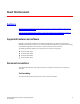
1 SIP SLB and call persistence using ServerIron ADX FIGURE 3 SIP server farm with DSR mode SIP Proxy Server G YIN TR F3 ING G RIN OK F5 F7 IN VI TE user1 F1 ServerIron F2 F4 L2/3 Infrastructure F1 SI OK F6 G TE VI IN IN NG RI OK F10 BYE F9 MEDIA RTP ACK F8 INVITE user2 From/To SIP Phone To/From VIP From/To SIP Phone To/From Real IP Figure 3 demonstrates a typical use case in which the ServerIron ADX application switch provides Call-ID based server persistence for UDP SIP
SIP SLB and call persistence using ServerIron ADX 1 NOTE The proxy server's IP address must be reachable from all SIP clients. User2's SIP phone receives the INVITE and alerts User2 of an incoming call. User2 replies with a Ringing message to the proxy server. If User2 answers the call, a 200 OK message is sent to the proxy server. The proxy server forwards this message to User1's SIP phone.
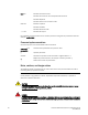
1 SIP SLB and call persistence using ServerIron ADX FIGURE 5 SIP Server Load Balancing with non-DSR mode OK F7 TRYING F3 INVITE F1 INVITE F2 RINGING F4 OK F6 RINGING F5 SIP Proxy Server SI TE I NV F3 G ServerIron F5 F7 F2 F6 F4 K O O G IN G K IN NG RI R IN TE G VI N YI TR IN I F1 ACK F8 MEDIA RTP user1 user2 BYE F9 OK F10 From/To SIP Phone To/From VIP To maintain session persistence and transaction integrity, this implementation has the following requirements: •
Configuring SIP SLB 1 SIP server health monitoring There are two types of SIP servers of particular importance: SIP proxy servers and SIP registrar servers. The ServerIron ADX supports advanced UDP Layer-7 application health checks for both server types. ServerIron ADX switches can be enabled to send REGISTER or OPTION messages to SIP servers to track their health.
1 Configuring SIP SLB Configuring a SIP proxy server and enabling health check Complete the following steps to configure a real SIP proxy server and its health check. 1. Configure a real server and IP address for a proxy server and enter the real server configuration mode. ServerIronADX(config)# server real proxy-server-1 1.1.3.1 Syntax: [no] server real 2. Specify the SIP port.
Configuring SIP SLB • • • • 1 health-check-method— Specifies the SIP health check method. options— Enables health check through OPTION messages. register— Enables health check through REGISTER messages (default method). health-check-no-dsr— Specifies for health check to be sent to a real server rather than a virtual server. Configuring a SIP proxy plus registrar server and enabling health check Complete the following steps to configure a real SIP proxy plus registrar server and its health check. 1.
1 Configuring SIP SLB NOTE You can specify SIP port number 5060 or the keyword sip. 3. Specify a redirect server and a health check method. ServerIronADX(config-rs-redirect-server-1)# port sip sip-redirect-server health-check-method register Syntax: port sip [sip-redirect-server] [options | health-check-method register] [health-check-no-dsr] • • • • • sip-redirect-server— Identifies the server as a SIP redirect server. health-check-method— Specifies the SIP health check method.
Configuring SIP SLB 1 5. Bind the real SIP proxy servers. ServerIronADX(config-vs-proxy-domain-1)# bind sip proxy-server-1 sip proxy-server-2 sip 6. Return to global configuration mode. ServerIronADX(config-vs-proxy-domain-1)# exit Configuring health check SIP health check can be performed by either the SIP REGISTER or OPTIONS method. Configure the method according to your needs. The default method is REGISTER.
1 Configuring SIP SLB Configuring the maximum number of SIP sessions ServerIronADX(config)# server sip session max-sip-sessions 1000000 Syntax: [no] server sip session max-sip-sessions The variable can be from 10 through 2,000,000 sessions. NOTE This command requires a reload. Removing this configuration using no command will reset the session to 500,000.
Configuring SIP SLB 1 Syntax: show sip server Use this command to display real server-related information. ServerIronADX# show sip server Avail.
1 Configuring SIP SLB FIGURE 6 Single TCP connection for each SIP request SIP Proxy Server TCP Connection Cal l-ID ... -ID1 1... Call ServerIron SIP phone Cal .. D2. all-I C l-ID 2... TCP Connection SIP phone SIP Proxy Server Client side: Connection reuse with Mega Proxy client Figure 7 shows several SIP requests being initiated by a Mega Proxy client. The Mega Proxy uses a single TCP connection to send all these requests. Each of these requests is identified using a unique SIP Call-ID.
Configuring SIP SLB FIGURE 7 1 Reuse of TCP connection ... -ID1 Call Mega-proxy SIP Proxy Server Call-ID1...Call-ID2...Call-ID3 ServerIron Call-ID2 Several SIP messages using one TCP Connection Ca ll-ID 3... SIP Proxy Server SIP Proxy Server Server-side connection: With source NAT If source NAT is enabled, then the ServerIron ADX uses source NAT IP addresses and ports for establishing connections with proxy servers.
1 Configuring SIP SLB Figure 8 shows how the ServerIron ADX performs reverse source NAT on SIP server-initiated traffic. FIGURE 8 SIP proxy server-initiated SIP requests SIP Proxy Server Cal l-ID ServerIron SIP phone 2... l-ID Cal 1... l-ID 1... Cal Cal l-ID 2...
Configuring SIP SLB 1 The command should adjust the default number of concurrent SIP transactions supported on a local barrel processor (BP). Normally, the default value is more than sufficient. Changing this value is not recommended. Real server commands for SIP over TCP The commands in this section are entered under the SIP real server configuration level. Use the following command to specify the maximum number of SIP connections allowed for a real server.
1 Configuring SIP SLB ServerIronADX(config-vs1)# port 5060 sip-alternative-port-start 5061 max-tcp-connections 3 Syntax: port sip-alternative-port-start max-tcp-connections <#connections> The is the virtual SIP port. Typically, this is port 5060. The variable specifies the beginning port of the alternate virtual port. This port will be used as the source-port of the client-side connection.
Configuring SIP SLB 1 Real server port configuration To configure keepalive from the real server port configuration, use the following commands. ServerIronADX(config)# server real proxy-server-1 ServerIronADX(config-rs-proxy-server-1)# port sip keepalive Syntax: port sip keepalive Configuring a DSCP value for SIP health checks During periods of network congestion, SIP health checks do not get high enough priority in a network, which causes servers to fail needlessly.
1 Configuring SIP SLB NOTE With this command, if the real server has been idling for the value or is not reachable due to health check, then it will be replaced with a new healthy real server on arrival of new packets to the hash bucket. The replacement algorithm attempts to achieve equal distribution of hash-buckets among available healthy real servers. The system will continue to assign idle or failed server hash-buckets to another healthy server until it reaches equilibrium.
Configuring SIP SLB 1 Example ServerIronADX# show server sip-hash proxy proxy-domain-1 SIP HashTable for virtual server : Summary for virtual port <5060>: ============================== RS|Port #buckets RS|Port #bucketss 172.16.1.
1 Configuring SIP SLB Debugging SIP sessions ServerIronADX# show sip debug session SIP Session Debug Counters SIP SESSION GET :4381 SIP SESS FREE LIST CORUPT :0 SIP SESS FINAL FREE :84 SIP SESS AGED :60 SIP SESS CORRUPT :0 SIP HA AGE SYNC RECV :0 SIP HA OUT OF IPC BUF :0 SIP HA SESS CREAT RECV :0 SIP HA DEL MSG RECV :0 SIP HA DEL ATTEMPT SENT :0 SIP HA CREATE EXIST :0 SIP SIP SIP SIP SIP SIP SIP SIP SIP SIP SIP SESSION GET FAILURE SESS INDEX INVALID SESS DEALLOC SESS ERR HA AGE SYNC ERR HA AGE SYNC SENT
SIP SLB command reference 1 Debugging UDP processes ServerIronADX# show sip debug udp-process SIP UDP Process Counters: UDP ERR :0 UDP NO HEADER UDP UNKNOWN PKT :0 UDP PKT TO MP UDP FWD DROP :55 UDP REV DROP UDP NO ACTION :0 :0 :0 :2 Syntax: show sip debug udp-process Debugging SIP packet traces The show sip debug packet-trace command shows the packets with the IP address of either or . The output displays packet processing starting from parsing to forwarding.
1 SIP SLB command reference Syntax: port sip {sip-redirect-server | sip-proxy-server | sip-registrar | sip-both-registrar-proxy-server} [health-check-method [options | register]] | [health-check-no-dsr] • • • • • • • • sip-redirect-server— Identifies the server as a SIP redirect server. sip-proxy-server— Identifies the server as a SIP proxy server. sip-registrar— Identifies the server as a SIP registrar. sip-both-registrar-proxy-server— Identifies the server as a SIP registrar or a proxy server.
Chapter* Transparent Cache Switching 2 In this chapter • Transparent cache switching overview . . . . . . . . . . . . . . . . . . . . . . . . . . . . . 29 • Other transparent cache switching options. . . . . . . . . . . . . . . . . . . . . . . . . . 41 • Other transparent cache switching options. . . . . . . . . . . . . . . . . . . . . . . . . . 41 • Policy-based caching . . . . . . . . . . . . . . . . . . . . . . . . . . . . . . . . . . . . . . . . . . . . 66 • Content-aware cache switching . . . . . .
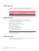
2 Transparent cache switching overview FIGURE 9 Logical representation of transparent caching Internet Web Servers www.rumors.com www.stockquotes.com www.news.com Border Access Router (BAR) Web Queries 208.95.8.3 Remote Access Router e18 (output port) SI e17 e4 e5 e16 e15 208.95.7.3 208.95.6.3 2001:db8::1 Cache Server 1 207.95.5.11 Cache Server 2 207.95.5.
Transparent cache switching overview 2 The cache server determines how the web query will be handled by pulling from its local information stores and facilitating that information with external web queries on the WAN, as needed, to complete the query. The ServerIron ADX provides the detection and switching of those HTTP packets forwarded from the cache server. This process is known as “transparent” cache switching because it is transparent to the end user.
2 Sample deployment topologies Advanced statistics Our TCS implementation provides the following advanced statistics: • • • • • Current connections on a per cache basis Peak connections on a per cache basis Total connections on a per cache basis Packet counts to and from cache on a per-cache basis Octet counts to and from cache on a per-cache basis Sample deployment topologies ServerIron ADX supports TCS in the following example topologies.
Sample deployment topologies 2 The following table lists the entries that need to be programmed in the CAM for hardware forwarding of pass-through traffic. TABLE 1 Required CAM programming for simple TCS configurations Level Match Hash 1 Destination port Source IP address 2 Source port Destination IP address TCS with spoofing In the following example configuration, the cache server is spoofing the client’s IP address instead of using its own IP address when accessing the real server.
2 Sample deployment topologies Client CIP ServerIron VIP 1a(CIP-RIP) Real Server RIP 2b(TIP-RIP) 3a(RIP-TIP) 4b(RIP-CIP) 3b(RIP-TIP) 2a(TIP-RIP) 4a(TIP-CIP) 1bDestNAT(CIP-TIP) CIP-Client IP Address RIP-Real Server IP Address VIP-Virtual IP Address TIP-Cache Server IP Address Transparent Cache Server TIP In Flow 1b, the ServerIron ADX changes the destination address in Flow 1a to that of the cache server. CAM programming is the same as for basic TCS, as detailed in Table 1.
Sample deployment topologies 2 In Flow 1b, the ServerIron ADX changes the source address to a configured IP address. The ServerIron ADX applies source NAT to the requests going from the ServerIron ADX to the cache server. Table 2 illustrates the CAM programming for this example.
2 Configuring transparent cache switching TABLE 3 Required CAM programming for VIPs with reverse proxy SLB enabled Level Match Hash 1 Destination IP = cache enabled VIP Source IP address 2 Source IP = cache enabled VIP Destination IP address 3 Destination port = cache port Source IP address 4 Source port = cache port Destination IP address Configuring transparent cache switching Transparent cache switching (TCS) is disabled by default. To set up TCS, perform the following tasks: 1.
Configuring transparent cache switching 2 • A cache group is defined in terms of input ports to the ServerIron ADX. To give a client access to a group of cache servers, the input port connecting the client to the ServerIron ADX must be in the cache group that contains the cache servers. If you plan to have only one cache group, you do not need to add the input ports to the cache group because all ports are members of cache group 1 by default.
2 Configuring transparent cache switching ServerIronADX(config)# server cache-name server1 ServerIronADX(config-rs-server1)# port http ServerIronADX(config-rs-server1)# port ssl ServerIronADX(config-rs-server1)# port 8080 Syntax: [no] port NOTE A maximum of 256 non-well-known ports (port number >1024) can be configured.
Configuring transparent cache switching 2 Assigning web cache servers to cache groups TCS requires all cache servers to belong to a cache group. To assign cache servers to a different cache group, use the server cache-group command. The ServerIron ADX uses one of two methods to distribute requests among the servers in a cache group: a hashing algorithm based on source and destination IP addresses or the least-connection method.
2 Configuring transparent cache switching Enabling transparent cache switching When TCS is enabled, the feature detects web traffic addressed for output to the Internet and redirects the traffic to the CPU, which processes the traffic and forwards it to the cache servers instead. TCS can be defined on either a global or local basis as described: • globally – If TCS is enabled on a global basis, all ports redirect web traffic toward the cache servers.
Other transparent cache switching options 2 In the following example, the ip policy command is configured to direct traffic locally. That IP policy is then configured under the interface configuration for ethernet port 18.
2 Other transparent cache switching options Removing an interface from a cache group You can remove an interface from a cache group to assign it to another cache group or to bias its traffic away from cache servers entirely. ServerIronADX(config)# interface ethernet 3 ServerIronADX(config-if-3)# no cache-group 1 Syntax: [no] cache-group Assigning an interface to a cache group To assign an interface to cache group, enter the following command.
Other transparent cache switching options 2 NOTE If you use content-aware cache switching (CSW in a TCS environment), URL string hashing is used to select a cache server within a server group. Content duplication is minimized because requests for cached content always go to the same cache server. Refer to “Active-standby TCS” on page 124 for more information. Distribution algorithm When a cache group contains multiple cache servers, the ServerIron ADX distributes traffic across the caches.
2 Other transparent cache switching options The ServerIron ADX contains 256 hash slots. If you do not assign weights to the cache servers (refer to “Setting the cache server weight” on page 59), the software divides the hash slots evenly among the cache servers. If you assign differing weights to the cache servers, the software assigns hash slots to the cache servers based on the ratios of their relative weights.
Other transparent cache switching options TABLE 4 2 Example TCS hash masks (IPv4+IPv6) (Continued) Destination mask ffff:ffff:ffff:ffff:: Source mask ::ffff Destination IP address Source IP address Cache server 2001:db8:0102:0303:7::1 Any C2 2001:db8:0102:0304:8::1 Any C3 2001:db8:0102:0303:6::1 2001:db8:0102:1 C1 2001:db8:0102:0303:7::1 2001:db8:0304:1 C1 2001:db8:0102:0304:8::1 2001:db8:0506:2 C2 Selecting server selection methods with cache groups By default, the SSL and HTTP pr
2 Other transparent cache switching options ServerIronADX(config)# server ServerIronADX(config-rs-cs2)# ServerIronADX(config-rs-cs2)# ServerIronADX(config-rs-cs2)# ServerIronADX(config-rs-cs2)# ServerIronADX(config-rs-cs2)# cache-name cs2 192.168.0.2 port http port http url "HEAD/" port ssl hc-track-group 80 443 exit In the following example, the cache selection method for the FTP protocol is changed to the hash method and it uses the same hash table as the HTTP protocol.
Other transparent cache switching options 2 Resilient hashing for maximum cache persistence In order to the maximize ‘cache-hit ratio’ which is a critical metric for architectures utilizing cache servers, most vendors of application delivery controllers (ADC) utilize a mechanism that provides persistence for traffic flows.
2 Other transparent cache switching options Cache route optimization Typically the ServerIron ADX sits between a border access router (BAR) and a remote access server (RAS) where the BAR connects to the Internet/intranet. The RAS forwards the client HTTP traffic to the ServerIron ADX, which redirects the traffic to the cache servers. When a border router is configured as the default router for the cache servers, all traffic sent towards the browsing clients behind the RAS must first go to the BAR.
Other transparent cache switching options 2 You can reduce the burden on the BAR by enabling cache route optimization. This feature configures the ServerIron ADX to use the information in its Layer 4 session table to recognize that the return traffic actually should go to the RAS instead of the BAR, and send the return traffic directly to the RAS. Thus, the return traffic does not needlessly add overhead to the BAR. FIGURE 10 Cache route optimization Internet Web servers www.oldnews.com 1.0.0.1 www.
2 Other transparent cache switching options • The route being used for the outgoing packet must not have been created or modified by an ICMP redirect, and must not be the router's default route. • The sub-net of the source IP address is the same as the sub-net of the next-hop IP address of the routed packet. • The packet must not be source routed. • The router must be configured to send redirects.
Other transparent cache switching options 2 Because this scheme works at the MAC layer, it is compatible with all routing protocols. Moreover, because the scheme is session specific, it can handle any number or RAS. When a session is terminated, the table entry is deleted and so is the “optimization”. Thus changes in the network at Layer 3 are immediately implemented.
2 Other transparent cache switching options Configuring destination NAT Destination NAT can be configured either under a cache server or a cache group as shown in the following commands: For a cache server ServerIronADX(config)# server cache-name server1 207.95.5.
Other transparent cache switching options 2 However, if the time since the last packet the ServerIron ADX sent to the cache server and the cache server’s response increases significantly, or the cache server’s reply never reaches the ServerIron ADX but instead takes an alternate path to the client, the ServerIron ADX assumes that the cache server has stopped responding. When this occurs, the ServerIron ADX marks the cache server FAILED and stops redirecting client queries to the cache server.
2 Other transparent cache switching options ServerIronADX(config)# server cache-group 1 ServerIronADX(config-tc-1)# source-nat ServerIronADX(config-tc-1)# dest-nat These commands configure a source IP address at the global CONFIG level of the CLI, then change the CLI to the cache group configuration level and enable source NAT and destination NAT. Source NAT configures the ServerIron ADX to change the source IP address in a client query from the client’s IP address to configured source IP address.
Other transparent cache switching options 2 each while CS4 through CS64 get two buckets each ([2 * 3] + [61 * 2] = 128). The result is that the original traffic handled by the cache server that went down is now distributed evenly among the remaining functional cache servers. The traffic on CS2 and CS3 increases by 2.34 percent ([131 128] / 128 = 2.34%), and by 1.56 percent on CS4 through S64 ([ 130 - 128] / 128 = 1.56%).
2 Other transparent cache switching options Enabling cache server spoofing support In TCS, when a client makes a request for HTTP content on the Internet, the ServerIron ADX directs the request to a cache server, rather than to the Internet. If the requested content is not on a cache server, it is obtained from a Web server of origin on the Internet, stored on a cache server to accommodate future requests, and sent from the cache server back to the requesting client.
Other transparent cache switching options 2 ServerIronADX# show cache-group Cache-group 1 has 1 members Admin-status = Enabled Active = 0 Hash_info: Dest_mask = 255.255.255.0 Src_mask = 0.0.0.0 Cache Server Name cs1 Admin-status L4-Hash-Buckets L7-Hash-Buckets 6 0 0 Name: cs1 IP: 192.168.1.
2 Other transparent cache switching options Optionally, you can direct the ServerIron ADX to send client requests to another available cache server in the same cache group that has not reached its maximum connection threshold without changing the current hash distribution. Use the reselect-server-if-overloaded command under the cache group configuration as shown in the following example.
Other transparent cache switching options 2 Setting the cache server weight You can assign a performance weight to each server. Servers assigned a higher weight receive a larger percentage of connections. To set the weight for cache server1 to 5 from the default value of 1, enter the following commands. ServerIronADX(config)# server cache-name server1 ServerIronADX(config-rs-server1)# weight 5 Syntax: weight The variable may have any value from 1 though 65000.
2 Other transparent cache switching options This example assumes that a source IP address is configured and source NAT and destination NAT also are enabled, if applicable. Shutting down a cache server The force shutdown feature (sometimes called the force delete feature) allows you to force termination of existing SLB connections. This feature assumes that you already have shut down a TCP/UDP service on the real server or you have shut down the real server itself.
Other transparent cache switching options 2 This option is simple because it does not require any configuration changes on the ServerIron ADX. However, this option immediately disconnects all users from the cache server, whereas the other options allow the server or service to gracefully shut down (unless you use the force shutdown option).
2 Other transparent cache switching options Traffic flow of passive FTP Using normal or passive FTP, a client begins a session by sending a request to communicate through TCP port 21, the port that is conventionally assigned for this use at the FTP server. This communication is known as the Control Channel connection. Figure 12 shows passive FTP packet flow. Using passive FTP, a PASV command is sent instead of a PORT command.
Other transparent cache switching options FIGURE 13 Client CIP 2 Basic TCS for passive FTP ServerIron ADX 1a Ctrl (CIP:x - RIP:21) 3b Ctrl (TIP:i - RIP:21) 2a Data (CIP:z - RIP:y) 4b Data (TIP:j - RIP:k) Real Server RIP 3a Ctrl (TIP:i - RIP:21) 4a Data (TIP:j - RIP:k) 1b Ctrl (CIP:x - RIP:21) 2b Data (CIP:z - RIP:y ) CIP-Client IP Address RIP-Real Server IP Address TIP-Cache Server IP Address Transparent Cache Server TIP TCS with spoofing In Figure 14, the cache server is spoofing the client
2 Other transparent cache switching options High availability support Because sessions are synced between ServerIron ADX devices, passive FTP for TCS also supports the high availability (HA) topology. The most common HA setup is Active-Active mode. Figure 15 shows an example of a Layer 2 Active-Active setup.
Other transparent cache switching options 2 If the R1 router or “ServerIron ADX 1” fails, the flow will switch as shown in Figure 18. FIGURE 18 Client R2 Failover flow SI2 Cache Server SI2 R2 Client During the failover, any traffic of the control or data channels will not be corrupted. After a short break, all transport will continue. Enabling passive FTP caching There is no specific CLI command to enable passive FTP caching.
2 Policy-based caching Policy-based caching Policy-based caching allows configuration of a separate set of filters for each cache group. Users can use access lists to define a set of filters and apply these to different cache groups. Creating a set of filters using access lists You first must create a set of filters using the access-list command at the CLI. You can use regular or extended access lists. Applying access lists to cache group Apply the access list to the desired cache group as follows.
Policy-based caching 2 Configuring an ACL to bypass caching You can configure a bypass filter to redirect traffic to the Internet instead of sending it to the cache servers. Configure an access list using the existing access-list CLI if you want to designate it as the bypass filter as follows. ServerIronADX(config)# server cache-bypass 3 Syntax: server cache-bypass [ipv6] The variable specifies the ID of the IPv4 or IPv6 ACL being used for bypass caching.
2 Content-aware cache switching NOTE The server debug-policy-caching command impacts performance and should be used for debugging purposes only. Output for this command is sent to the BP. Content-aware cache switching Content-aware cache switching (CSW in a TCS environment) uses information in the header of an HTTP request to determine how or if content should be retrieved from a cache server.
Content-aware cache switching 2 The ServerIron ADX can examine both the URL string and Host header field when determining where to send the HTTP request. Refer to RFC 1945 or RFC 2616 for more information on HTTP request messages. The selection criteria in a policy can be a string of characters starting from the beginning of the URL string, the end of the URL string, or within any part of the URL string. For example, selection criteria can be a URL string that starts with the text “/home”.
2 Content-aware cache switching FIGURE 19 Content-aware cache switching Internet BAR Web Queries RAS SI CacheServer1 192.168.1.101 CacheServer2 192.168.1.102 Server Group ID=1 Client requests for URLs that end with gif are directed to one of the cache servers in this server group CacheServer3 192.168.1.
Content-aware cache switching 2 1. Because the URL begins with "gif", the CSW policy directs the request to one of the cache servers in Server Group ID=1. 2. The ServerIron ADX hashes the URL string, selecting the same server it selected previously. 3. This time the cache server has the content and does not have to go to the Internet to get it; it sends the cached content to the requesting client. Setting up content-aware cache switching consists of the following steps. 1.
2 Content-aware cache switching NOTE In addition to using text as selection criteria, you can use an asterisk (*) as a wildcard character to specify one or more characters at the end of a URL string. For example, using "/ho*" as the selection criteria matches /home, /hotels, and /home/main/index.html. If you are using the suffix matching method, you cannot use an asterisk (*) as a wildcard character. The asterisk wildcard character is valid for the prefix and pattern matching methods only.
Content-aware cache switching 2 The port http group-id command indicates the server groups to which the cache server belongs. The server group is expressed as a pair of numbers, indicating a range of server group IDs. The first number is the lowest-numbered server group ID, and the second is the highest-numbered server group ID. For example, if a cache server belongs only to the server group with ID = 1, the last two numbers in the port http group-id command would be 1 1.
2 Content-aware cache switching • If a cache server with the matching server group-id is not found, but a default CSW rule with forward action is specified, then the HTTP request is forwarded to a cache server defined inside the default rule. • If a cache server with the matching server group-id is not found, and a default CSW rule with forward action is not specified, then the HTTP request is forwarded to any available cache server within the cache-group.
Content-aware cache switching 2 When group-failover is enabled: if cache1 goes down, then the request is matched against the default rule, and directed to 'cache2'. If cache2 was also down, then the request is sent to any available cache server defined under 'cache-group 1' (such as 'cache3' in this example). Configuring policies for dynamic content For dynamic web pages such as Active Server Pages, it may be preferable not to cache the content.
2 Content-aware cache switching FIGURE 20 Sending requests for Active Server Pages to the Internet Internet Client requests for URLs that contain asp anywhere within are directed to the Internet BAR Web Queries RAS SI CacheServer1 192.168.1.101 CacheServer2 192.168.1.102 CacheServer3 192.168.1.
Content-aware cache switching 2 ServerIronADX(config)# csw-rule r1 url pattern “asp” ServerIronADX(config)# csw-policy policyA1 ServerIronADX(config-csw-policyA1)# match forward 0 ServerIronADX(config-csw-policyA1)# default forward 100 ServerIronADX(config-csw-policyA1)# exit The pattern method in the csw-rule r1 url command causes the policy to look for the selection criteria anywhere within the URL string.
2 Content-aware cache switching Once this feature is enabled, the ServerIron ADX categorizes port 80 traffic as either true HTTP traffic or non-HTTP traffic: • If the traffic is identified as HTTP traffic, then subsequent packets are processed normally using transparent cache switching. • If the traffic is identified as non-HTTP traffic masquerading over port 80, then subsequent packets are bypassed to the Internet.
2 Content-aware cache switching Displaying HTTP keep-alive statistics You can use the show server proxy keep-alive command to display HTTP keep-alive statistics. The statistics relevant to HTTP keep-alive are shown (in bold) in the following abbreviated output and described in Table 5. ServerIronADX 1000#show server proxy keep-alive Keep-alive connection statistics: ...
2 Cache persistence using URL hashing ServerIronADX# clear server keep-alive statistics Syntax: clear server keep-alive statistics Cache persistence using URL hashing The ServerIron ADX enables traffic distribution among cache servers in a TCS setup after inspecting and hashing based on the request URL. This enables cache persistence based on the requested URL and minimizes duplication of content among multiple cache servers. The hashing can be done on a complete URL or a portion of the URL.
Cache persistence using URL hashing 2 1. Get http://login.yahoo.com/config/mail?.src=ym HTTP 1.1 2. Get /config/mail?.src=ym Host: login.brocade.com The following table demonstrates which part of the string would be used for hashing either of the prior examples depending the method selected with the csw-hash url command. TABLE 6 Hashing methods Method String used for hashing Complete login.brocade.com/confg/mail?.src=ym path-only config/mail path-and-parameters confg/mail?.
2 Cache persistence using URL hashing NOTE Because hash-persist action is a secondary action, you must add a forward action as shown in the following example, before adding a hash-persist action.
Cache persistence using URL hashing 2 With this command, the third step is for the system to parse the URL string up-to a character defined by the value of the . The delimiter string is used to define the end pattern after finding the substring. If the rest of URL string has multiple delimiter strings, only the first one will be used.
2 Cache persistence using URL hashing ServerIronADX(config-csw-p1)# match r1 forward 1 ServerIronADX(config-csw-p1)# match r1 hash-persist url search-url “v=” offset 0 length 16 TABLE 7 Results for parsing the entire URL by method Method String used for hashing pattern string only bUfp24dwzOA&playnext=1&videos=XA7MyzKoQXQ&feature=featured pattern string with a delimiter of “&” cbUfp24dwzOA pattern string with a length value of “16” bUfp24dwzOA&play Parsing the host string Parsing the host strin
Cache persistence using URL hashing 2 system will start the second step. The second step in the process is to adjust the starting place on the URL string by moving it by the number of characters defined by a value specified in the . If the pattern string is empty, the system will not search the pattern part, and use the beginning of URL string as the start point of the third step.
2 Cache persistence using URL hashing ServerIronADX(config-csw-p1)# match r1 hash-persist url search-host “www.” offset 0 length 5 Syntax: [no] hash-persist url search-url offset length The contents of the variable is the same as described in “Parsing using the “pattern string” only”. The contents and operation of the is the same as described in “Parsing using the “pattern string” only”.
Traffic distribution based on cache server capacity 2 ServerIron ADX supports multiple pattern search for the same rule. Support is provided for up to 4 different pattern strings as shown in the following example.
2 Traffic distribution based on cache server capacity The following are some guidelines for using this feature: • This feature can only be used for HTTP traffic over port 80. • By default, the cache server state is set to OFFLINE. If an out-of-range SNMP MIB value is received, the cache server state is set to the default state (OFFLINE). • Only SNMPv2 is currently supported • Layer 7 SNMP functionality (as shown in Table 11) only applies at the time a new server is selected.
Traffic distribution based on cache server capacity 2 • Within the cache server configuration: • Set the SNMP request community string to the same as the cache server. • Set the SNMP request oid of the cache server. • Within the cache group configuration, set the predictor to be SNMP weighted. The following configuration sets the SNMP request community string and OID. NOTE This example shows commands that are valid on the ServerIron ADX device only when it is running the Layer 3 router image.
2 Traffic distribution based on cache server capacity 1. ServerIron ADX sends periodic SNMP queries to the cache server. 2. ServerIron ADX sets the cache server state based on the reply it receives from the cache server. 3. For an incoming connection, a hash is computed based on its load state.
Displaying cache information 2 Displaying cache information To display cache information, enter the following command at any level of the CLI. Cache-group 1 has 1 members Admin-status = Enabled Active = 0 Hash_info: Dest_mask = 255.255.255.0 Src_mask = 0.0.0.0 Cache Server Name cs1 Admin-status L4-Hash-Buckets L7-Hash-Buckets 6 0 0 Name: cs1 IP: 192.168.1.
2 Displaying cache information ServerIronADX# show cache-group Cache-group 1 has 1 members Admin-status = Enabled Hash_info: Dest_mask = 255.255.255.0 Src_mask = 0.0.0.0 Cache Server Name cs1 cs2 cs3 Admin-status 6 6 6 Hash-distribution L7-hash-distribution 4 21 3 22 4 21 HTTP Traffic From <-> to Web-Caches ===================================== Name: cf Client Web-Server Total IP: 209.157.23.
Displaying cache information TABLE 12 2 TCS information (Continued) Field Description Cache Server Name The names of the cache servers in the cache group. These are the names you assigned when you configured cache server information on the ServerIron ADX.
2 Sample configurations TABLE 12 TCS information (Continued) Field Description Traffic statistics for traffic between clients and web servers The statistics for this section are for traffic that did not go to the cache server. Generally, statistics in this section accumulate when the cache server is not available. When the cache server is not available, the ServerIron ADX sends client requests directly to the network or Internet for servicing by the web servers.
Sample configurations 2 Basic TCS configuration Figure 21 shows a configuration in which HTTP traffic flows into a Point-of-Presence (POP) from Remote Access Servers (RASs) and out of the POP to the Internet through a Border Access Router (BAR). The cache servers are labeled C1, C2, and C3. FIGURE 21 Basic TCS configuration example Internet Remote Access Server (RAS) The CAR connects the clients (through the ServerIron) to the cache servers.
2 Sample configurations In this example, suppose you want all traffic to be cached and you want to use the ServerIron ADX’s default settings. To configure the ServerIron ADX for this example, you define the caches, assign them to cache groups, and apply an IP policy. Applying IP policies For the simple case in which you want to cache everything no matter where it comes from or where it is going to, use a global policy, such as the following.
Sample configurations 2 All ports on the ServerIron ADX are assigned to cache group 1 by default. Ports can be assigned to any cache group (only one at a time) or removed from all cache groups. If a port is removed from all cache groups, traffic entering on that port is not be redirected to a cache because rule 1 in this example is not true. Once the caches have been defined, they must be associated (bound) with a particular cache group.
2 Sample configurations Now RAS-to-BAR traffic is still cached because the input ports are in the default cache group and the output ports have the IP policy applied. BAR-to-RAS and RAS-to-RAS traffic is not cached because rule 2 is still false. BAR-to-BAR traffic is not cached because rule 1 is false.
Sample configurations 2 Policy-based caching Policy-based caching enables you to selectively cache some web sites but not others, on specific cache servers. For example, an ISP can use a ServerIron ADX configured for policy-based caching to redirect HTTP traffic to a series of web cache servers made by different vendors with different caching criteria.
2 Sample configurations Policy-based caching configuration The following configuration implements the topology described in Figure 22. NOTE This example shows commands that are valid on the ServerIron ADX device only when it is running the Layer 3 router image.
Sample configurations 2 You can override this behavior by enabling the FastCache feature. This feature configures the ServerIron ADX to continue redirecting client requests to a cache server even though the ServerIron ADX does not see responses from the cache server. You enable the feature individually for real servers. NOTE Even when use the FastCache feature, the ServerIron ADX still performs a Layer 3 health check by regularly pinging the cache server.
2 Sample configurations ServerIronADX(config)# server cache-name cacheserver4 209.157.22.215 ServerIronADX(config-rs-cacheserver4)# exit ServerIronADX(config)# server cache-name cacheserver5 209.157.22.225 ServerIronADX(config-rs-cacheserver5)# exit This example assumes that the cache contains the contents requested by the client. However, if the cache does not contain the requested page, the cache tries to get the page from the live web site.
Sample configurations 2 • If the cache server is unavailable or does not have the page and thus attempts to send the request back through the ServerIron ADX to the Internet, the ServerIron ADX sends the request to the router for forwarding to the Internet. If the virtual IP address is not configured on the ServerIron ADX, the ServerIron ADX drops the request from the cache server. Figure 24 shows an example of a configuration that requires CFO.
2 Sample configurations The variable specifies an IPv6 address for the virtual IP address of the cache group. An IPv6 virtual IP address can only be configured under an IPv6 cache group. TCS with reverse proxy TCS with reverse proxy relieves clients who have configured their web browsers to point to a proxy server from the need to reconfigure their browsers.
Sample configurations 2 Internet Client browers A, B, and C do not use a proxy address. The ServerIron transparently switches client requests for web site IP addresses to a cache server based on the hash mask. BAR A C B RAS D E SI F Client browsers D, E, and F are configured to use proxy address 209.157.22.2 The ServerIron receives requests from these clients on the VIP, which is configured as the proxy server. The ServerIron then load balances the requests to the cache servers.
2 Sample configurations NOTE This example shows commands that are valid on the ServerIron ADX device only when it is running the Layer 3 router image.
High availability designs with TCS 2 High availability designs with TCS Layer 3 TCS The following sections illustrate Layer 3 TCS support in the following configurations: • • • • “Layer 3 basic TCS configuration” on page 107 “Layer 3 active-active TCS configuration” on page 108 “Layer 3 active-active TCS configuration with a remote cache server” on page 112 “Layer 3 Sym-Active SLB with TCS” on page 115 Layer 3 basic TCS configuration Figure 26 illustrates a basic Layer 3 TCS configuration.
2 High availability designs with TCS ServerIronADX(config)# vlan 100 by port ServerIronADX(config-vlan-100)# untagged ethe 1/1 to 1/4 ethe 2/1 to 2/4 ServerIronADX(config-vlan-100)# router-interface ve 1 ServerIronADX(config-vlan-100)# exit ServerIronADX(config)# vlan 200 by port ServerIronADX(config-vlan-200)# untagged ethe 1/5 to 1/7 ethe 2/5 to 2/7 ServerIronADX(config-vlan-200)# router-interface ve 2 ServerIronADX(config-vlan-200)# exit ServerIronADX(config)# interface ve 1 ServerIronADX(config-ve-1)#
2 High availability designs with TCS SI 10.10.20.3 untag e 1/1-1/4 ve 1 untag e 1/1-1/4 ve 1 ServerIron A SI 10.10.20.1 Port e7 Active-Active Link 195.92.20.104 195.92.20.102 ve 3 3.3.3.1 Cache3 3.3.3.22 ve 1 3.3.3.2 Port e1 Port e5 Router VRRP-E on 10.10.10.10 10.10.20.2 10.10.10.3 untag e 1/5-1/7 ve 2 B 10.10.10.1 VRRP-E on 3.3.3.10 Port e1 Router VRRP-E on 10.10.20.10 untag ve 1 ServerIron Port e22 172.32.1.1 untag e 1/5-1/7 ve 2 ve 1 Port e1 10.10.10.
2 High availability designs with TCS ServerIronADX(config)# interface ve 2 ServerIronADX(config-ve-2)# ip address 10.10.10.1 255.255.255.0 ServerIronADX(config-ve-2)# ip vrrp-extended vrid 2 ServerIronADX(config-ve-2-vrid-2)# backup ServerIronADX(config-ve-2-vrid-2)# ip-address 10.10.10.
High availability designs with TCS 2 ServerIronADX(config)# vlan 500 by port ServerIronADX(config-vlan-500)# untagged ethe 1/8 to 1/12 ServerIronADX(config-vlan-500)# router-interface ve 3 ServerIronADX(config-vlan-500)# exit ServerIronADX(config)# vlan 16 by port ServerIronADX(config-vlan-16)# untagged ethe 1/16 ServerIronADX(config-vlan-16)# static-mac-address 00e0.52ee.6900 ethernet 1/16 ServerIronADX(config-vlan-16)# exit ServerIronADX(config)# interface ve 1 ServerIronADX(config-ve-1)# ip address 10.
2 High availability designs with TCS Layer 3 active-active TCS configuration with a remote cache server Figure 28 illustrates an active-active TCS configuration with a remote cache server. FIGURE 28 Active-active TCS configuration with remote cache server untag e 1/1-1/4 ve 1 SI 10.10.20.1 Port e7 Active-Active Link 10.10.20.2 10.10.20.104 Internet ve 3 3.3.3.1 Cache3 3.3.3.22 ve 1 3.3.3.2 Port e1 Port e5 Router VRRP-E on 10.10.10.10 Port e1 Router 10.10.10.1 VRRP-E on 3.3.3.
High availability designs with TCS 2 ServerIronADX(config-ve-1-vrid-1)# ip-address 10.10.20.10 ServerIronADX(config-ve-1-vrid-1)# track-port ve 2 ServerIronADX(config-ve-1-vrid-1)# track-port ve 3 ServerIronADX(config-ve-1-vrid-1)# enable ServerIronADX(config)# interface ve 2 ServerIronADX(config-ve-2)# ip address 10.10.10.1 255.255.255.0 ServerIronADX(config-ve-2)# ip vrrp-extended vrid 2 ServerIronADX(config-ve-2-vrid-2)# backup ServerIronADX(config-ve-2-vrid-2)# ip-address 10.10.10.
2 High availability designs with TCS ServerIronADX(config)# vlan 200 by port ServerIronADX(config-vlan-200)# untagged ethe 1/5 to 1/7 ServerIronADX(config-vlan-200)# router-interface ve 2 ServerIronADX(config-vlan-200)# exit ServerIronADX(config)# vlan 500 by port ServerIronADX(config-vlan-500)# untagged ethe 1/8 to 1/12 ServerIronADX(config-vlan-500)# router-interface ve 3 ServerIronADX(config-vlan-500)# exit ServerIronADX(config)# vlan 16 by port ServerIronADX(config-vlan-16)# untagged ethe 1/16 ServerI
High availability designs with TCS 2 Layer 3 Sym-Active SLB with TCS Figure 29 illustrates a Sym-Active configuration with TCS, using VRRPE. NOTE To allow failover and session synchronization in an Sym-Active configuration to work properly, there must be a Layer 2 connection between the two ServerIron ADXs. This connection is required so that Layer 2 broadcasts, including ARP to the VIP from the ServerIron ADX with lower symmetric priority, can be exchanged between the two ServerIron ADXs.
2 High availability designs with TCS NetIron(config)# vlan 1 name DEFAULT-VLAN by port NetIron(config-vlan-1)# router-interface ve 1 NetIron(config-vlan-1)# exit NetIron(config)# vlan 2 by port NetIron(config-vlan-2)# untagged ethe 1 to 2 NetIron(config-vlan-2)# router-interface ve 2 NetIron(config-vlan-2)# exit NetIron(config)# vlan 23 by port NetIron(config-vlan-23)# untagged ethe 23 NetIron(config-vlan-23)# exit NetIron(config)# interface ve 1 NetIron(config-ve-1)# ip address 172.1.1.3 255.255.255.
High availability designs with TCS 2 ServerIronADX(config)# vlan 16 by port ServerIronADX(config-vlan-16)# untagged ethe 3/16 ServerIronADX(config-vlan-16)# static-mac-address 00e0.5212.3400 ethernet 3/16 ServerIronADX(config-vlan-16)# exit ServerIronADX(config)# vlan 999 by port ServerIronADX(config-vlan-999)# untagged ethe 3/24 ServerIronADX(config-vlan-999)# exit ServerIronADX(config)# interface ve 1 ServerIronADX(config-ve-1)# ip address 100.1.1.252 255.255.255.
2 High availability designs with TCS ServerIronADX(config)# server port 443 ServerIronADX(config-port-443)# session-sync ServerIronADX(config-port-443)# tcp ServerIronADX(config-port-443)# exit ServerIronADX(config)# server router-ports ethernet 3/1 ServerIronADX(config)# server router-ports ethernet 3/3 ServerIronADX(config)# server real rs29 100.1.1.
High availability designs with TCS 2 ServerIronADX(config-vs-www)# bind http rs31.1 http rs30.1 http rs29.1 http rs30 http ServerIronADX(config-vs-www)# bind http rs31 http rs29 http ServerIronADX(config-vs-www)# exit ServerIronADX(config)# server virtual-name-or-ip ftp 10.2.24.102 ServerIronADX(config-vs-ftp)# sym-priority 254 ServerIronADX(config-vs-ftp)# sym-active ServerIronADX(config-vs-ftp)# port ftp ServerIronADX(config-vs-ftp)# bind ftp rs31.1 ftp rs30.1 ftp rs29.
2 High availability designs with TCS NOTE This example shows commands that are valid on the ServerIron ADX device only when it is running the Layer 3 router image.
High availability designs with TCS 2 ServerIronADX(config)# vlan 1 name DEFAULT-VLAN by port ServerIronADX(config-vlan-1)# router-interface ve 1 ServerIronADX(config-vlan-1)# exit ServerIronADX(config)# vlan 2 by port ServerIronADX(config-vlan-2)# untagged ethe 3/1 ethe 3/3 ethe 4/1 ethe 4/3 ServerIronADX(config-vlan-2)# router-interface ve 2 ServerIronADX(config-vlan-2)# exit ServerIronADX(config)# vlan 16 by port ServerIronADX(config-vlan-16)# untagged ethe 3/16 ServerIronADX(config-vlan-16)# static-mac
2 High availability designs with TCS ServerIronADX(config)# server port 1755 ServerIronADX(config-port-1755)# session-sync ServerIronADX(config-port-1755)# tcp ServerIronADX(config-port-1755)# udp ServerIronADX(config-port-1755)# exit ServerIronADX(config)# server port 53 ServerIronADX(config-port-53)# session-sync ServerIronADX(config-port-53)# exit ServerIronADX(config)# server port 443 ServerIronADX(config-port-443)# session-sync ServerIronADX(config-port-443)# tcp ServerIronADX(config-port-443)# exit
High availability designs with TCS 2 ServerIronADX(config-rs-rs31.1)# port http url "HEAD /" ServerIronADX(config-rs-rs31.1)# port mms ServerIronADX(config-rs-rs31.1)# port ssl ServerIronADX(config-rs-rs31.1)# exit ServerIronADX(config)# server virtual-name-or-ip www 10.2.24.100 ServerIronADX(config-vs-www)# sym-priority 254 ServerIronADX(config-vs-www)# sym-active ServerIronADX(config-vs-www)# predictor round-robin ServerIronADX(config-vs-www)# port http ServerIronADX(config-vs-www)# bind http rs31.
2 High availability designs with TCS ServerIronADX(config)# server cache-group 1 ServerIronADX(config-tc-1)# prefer-router-cnt 0 ServerIronADX(config-tc-1)# cache-name cache1 ServerIronADX(config-tc-1)# cache-name cache2 ServerIronADX(config-tc-1)# no http-cache-control ServerIronADX(config-tc-1)# exit Active-standby TCS TCS is supported in an active-standby configuration. Figure 27 illustrates a sample active-standby TCS configuration.
High availability designs with TCS 2 ServerIronADX(config)# vlan 24 by port ServerIronADX(config-vlan-1)# untagged ethe 24 ServerIronADX(config-vlan-1)# router-interface ve 4 ServerIronADX(config-vlan-1)# exit ServerIronADX(config)# ip route 195.90.5.0 255.255.255.0 195.92.10.7 ServerIronADX(config)# interface ve 1 ServerIronADX(config-ve-1)# ip address 195.92.10.1 255.255.255.0 ServerIronADX(config-ve-1)# exit ServerIronADX(config)# interface ve 2 ServerIronADX(config-ve-2)# ip address 195.92.20.1 255.
2 Interoperability issues with cache servers NOTE This example shows commands that are valid on the ServerIron ADX device only when it is running the Layer 3 router image.
Interoperability issues with cache servers 2 NetCache servers When the ServerIron ADX sends a packet to a NetCache server, by default the server addresses its replies to the packet to the source MAC address of the packet, instead of replying to the MAC address of the server's default gateway. This causes problems, especially in one-arm routing configurations. To work around this issue, enter the following commands on the NetCache server. priv set advanced show config.system.fast_ip.enable set config.
2 128 Interoperability issues with cache servers ServerIron ADX Advanced Server Load Balancing Guide 53-1002435-03