53-1001540-04 31 May 2012 Brocade VA-40FC Hardware Reference Manual ®
© 2012 Brocade Communications Systems, Inc. All Rights Reserved. Brocade, Brocade Assurance, the B-wing symbol, DCX, Fabric OS, MLX, SAN Health, VCS, and VDX are registered trademarks, and AnyIO, Brocade One, CloudPlex, Effortless Networking, ICX, NET Health, OpenScript, and The Effortless Network are trademarks of Brocade Communications Systems, Inc., in the United States and/or in other countries. Other brands, products, or service names mentioned may be trademarks of their respective owners.
Contents About This Document In this chapter . . . . . . . . . . . . . . . . . . . . . . . . . . . . . . . . . . . . . . . . . . . vii How this document is organized . . . . . . . . . . . . . . . . . . . . . . . . . . . . vii Supported hardware and software . . . . . . . . . . . . . . . . . . . . . . . . . . vii What’s new in this document . . . . . . . . . . . . . . . . . . . . . . . . . . . . . . . viii Document conventions . . . . . . . . . . . . . . . . . . . . . . . . . . . . . . . . . . . .
Product Name configuration . . . . . . . . . . . . . . . . . . . . . . . . . . . . . . . 13 Providing power to the switch . . . . . . . . . . . . . . . . . . . . . . . . . . . 13 Creating a serial connection . . . . . . . . . . . . . . . . . . . . . . . . . . . . 13 Switch IP address. . . . . . . . . . . . . . . . . . . . . . . . . . . . . . . . . . . . . 14 Date and time settings . . . . . . . . . . . . . . . . . . . . . . . . . . . . . . . . 15 Chapter 3 Brocade VA-40FC Operation In this chapter . . . .
Regulatory compliance . . . . . . . . . . . . . . . . . . . . . . . . . . . . . . . . . . . . 32 FCC warning (US only) . . . . . . . . . . . . . . . . . . . . . . . . . . . . . . . . . 33 KCC statement (Republic of Korea) . . . . . . . . . . . . . . . . . . . . . . 33 VCCI statement Japan . . . . . . . . . . . . . . . . . . . . . . . . . . . . . . . . . 33 Power cords (Japan Denan). . . . . . . . . . . . . . . . . . . . . . . . . . . . . 34 China statement. . . . . . . . . . . . . . . . . . . . . . . . . .
vi Brocade VA-40FC Hardware Reference Manual 53-1001540-04
About This Document In this chapter • How this document is organized . . . . . . . . . . . . . . . . . . . . . . . . . . . . . . . . . . vii • Supported hardware and software. . . . . . . . . . . . . . . . . . . . . . . . . . . . . . . . . vii • What’s new in this document . . . . . . . . . . . . . . . . . . . . . . . . . . . . . . . . . . . . . viii • Document conventions . . . . . . . . . . . . . . . . . . . . . . . . . . . . . . . . . . . . . . . . . . viii • Notice to the reader . . . . . . . . . . . .
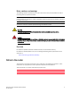
What’s new in this document The Chinese regulatory statement has been added. “China statement.” Document conventions This section describes text formatting conventions and important notice formats used in this document.
Notes, cautions, and warnings The following notices and statements are used in this manual. They are listed below in order of increasing severity of potential hazards. NOTE A note provides a tip, guidance or advice, emphasizes important information, or provides a reference to related information. ATTENTION An Attention statement indicates potential damage to hardware or data. CAUTION A Caution statement alerts you to situations that can be potentially hazardous to you.
Additional information This section lists additional Brocade and industry-specific documentation that you might find helpful. Brocade resources To get up-to-the-minute information, go to http://my.brocade.com and register at no cost for a user ID and password. For additional Brocade documentation, visit the Brocade SAN Info Center and click the Resource Library location: http://www.brocade.com Release notes are available on the My Brocade website (http://my.brocade.
Getting technical help Contact your switch support supplier for hardware, firmware, and software support, including product repairs and part ordering. To expedite your call, have the following information available: 1.
Document feedback Quality is our first concern at Brocade and we have made every effort to ensure the accuracy and completeness of this document. However, if you find an error or an omission, or you think that a topic needs further development, we want to hear from you. Forward your feedback to: documentation@brocade.com Provide the title and version number of the document and as much detail as possible about your comment, including the topic heading and page number and your suggestions for improvement.
Chapter 1 Brocade VA-40FC Introduction In this chapter • Brocade VA-40FC overview . . . . . . . . . . . . . . . . . . . . . . . . . . . . . . . . . . . . . . . . • Port side of the Brocade VA-40FC . . . . . . . . . . . . . . . . . . . . . . . . . . . . . . . . . . • Non-port side of the Brocade VA-40FC . . . . . . . . . . . . . . . . . . . . . . . . . . . . . . • Field replaceable units (FRUs) . . . . . . . . . . . . . . . . . . . . . . . . . . . . . . . . . . . . . • Ports on Demand license . . . . . .
1 Brocade VA-40FC overview • Single motherboard design with 667 MHz PowerPC 440EPx Reduced Instruction Set Computer (RISC) CPU and integrated peripherals which provide high performance. • Inter-Switch Link (ISL) Trunking (licensable), which allows up to eight ports (at 1, 2, 4, or 8 Gbps speeds) between a pair of switches combined to form a single, logical ISL with a speed of up to 128 Gbps full duplex for optimal bandwidth utilization and load balancing.
1 Port side of the Brocade VA-40FC Port side of the Brocade VA-40FC The port side of the Brocade VA-40FC includes the system status LED, console port, Ethernet port and LEDs, USB port, and Fibre Channel ports and the corresponding port status LEDs. Figure 1 shows the port side of the Brocade VA-40FC.
1 Non-port side of the Brocade VA-40FC Port Numbering The Fibre Channel ports on the Brocade VA-40FC are numbered from left to right, in eight-port groups from 0 to 39 as illustrated in Figure 2. 0 1 2 3 8 9 10 11 16 17 18 19 24 25 26 27 32 33 34 35 4 5 6 7 12 13 14 15 20 21 22 23 28 29 30 31 36 37 38 39 FIGURE 2 Port Numbering on the Brocade VA-40FC ATTENTION Brocade ISL Trunking is licensed software that allows you to create trunking groups of ISLs between adjacent switches.
Field replaceable units (FRUs) FIGURE 3 1 Non-port side view of the Brocade VA-40FC Field replaceable units (FRUs) The Brocade VA-40FC has two integrated power supply/fan unit field replaceable units (FRUs). These power supply/fan assembly units are hot-swappable and redundant, and are capable of functioning universally without voltage jumpers or switches. The FRU units are identical and interchangeable.
1 ISL trunking groups For detailed information on enabling additional ports using the POD license, refer to the Fabric OS Administrator’s Guide. ISL trunking groups The Product Name supports Interswitch Link (ISL) Trunking as a licensed feature. When this feature is enabled, you can create trunked groups of up to eight contiguous ports, permitting a speed of up to 64 Gbps (128 Gbps full duplex).
Fabric OS Native and Access Gateway modes 1 • In Fabric OS Native mode, the switch provides up to 40 external autosensing (2, 4 and 8 Gbps) Fibre Channel ports. These universal and self-configuring ports are capable of becoming one of the following port types: - F_Port (fabric enabled) FL_Port (fabric loop enabled) E_Port (expansion port) • In Access Gateway mode, the switch provides up to 40 autosensing (2, 4, and 8 Gbps) Fibre Channel ports.
1 Fabric OS Native and Access Gateway modes Enabling Access Gateway mode Note the following when enabling Access Gateway mode: • After you enable AG mode, some fabric information is erased, such as the zone and security databases. • Enabling AG mode is disruptive because the switch is disabled and rebooted. • Ensure that no zoning or Admin Domain (AD) transaction buffers are active.
Chapter Brocade VA-40FC Installation and Configuration 2 In this chapter • Items included with the Product Name . . . . . . . . . . . . . . . . . . . . . . . . . . . . . . 9 • Installation and safety considerations . . . . . . . . . . . . . . . . . . . . . . . . . . . . . . . 9 • Installing a standalone Product Name. . . . . . . . . . . . . . . . . . . . . . . . . . . . . . 12 • Cabinet installation for a Product Name . . . . . . . . . . . . . . . . . . . . . . . . . . . .
2 Installation and safety considerations Electrical considerations To install and operate the switch successfully, ensure the following: • The primary outlet is correctly wired, protected by a circuit breaker, and grounded in accordance with local electrical codes. • The supply circuit, line fusing, and wire size are adequate, as specified by the electrical rating on the switch nameplate. • The power supply standards provided in Table 5, “Power Supply Specifications” on page 29 are met.
Installation and safety considerations 2 Recommendations for cable management The minimum bend radius for a 50 micron cable is 2 inches under full tensile load and 1.2 inches with no tensile load. Cables can be organized and managed in a variety of ways. For example, you can use cable channels on the sides of the cabinet or patch panels to minimize cable management. Following is a list of recommendations: NOTE You should not use tie wraps with optical cables because they are easy to over tighten.
2 Installing a standalone Product Name Installing a standalone Product Name Perform this task to install the Product Name as a standalone unit. 1. Unpack the Product Name and verify the items listed on “Items included with the Product Name” on page 9. Verify the items are present and undamaged. 2. Apply the adhesive rubber feet. Applying the rubber feet onto the switch helps prevent the switch from sliding off the supporting surface. a.
Product Name configuration 2 Product Name configuration Once you have set up the Product Name in a rack or as a standalone switch, it is time to give it power and a basic configuration. If you are going to use the Product Name in a single-switch setup, you can use EZSwitchSetup to complete the basic configuration. See the EZSwitchSetup CD, included with the Product Name for more information. You can also use the Brocade VA-40FC Quickstart Guide.
2 Product Name configuration 2.
Product Name configuration 2 3. Complete the rest of the network information as prompted. Ethernet Subnetmask: [255.255.255.0] Ethernet IP Address: [192.168.74.102] Ethernet Subnetmask: [255.255.255.0] 4. Enter off to Disable DHCP when prompted. DHCP [OFF]: off Date and time settings The Product Name maintains the current date and time inside a battery-backed real-time clock (RTC) circuit. Date and time are used for logging events.
2 Product Name configuration Local time synchronization You can synchronize the local time of the principal or primary fabric configuration server (FCS) switch to a maximum of eight external network time protocol (NTP) servers. To keep the time in your SAN current, it is recommended that the principal or primary FCS switch has its time synchronized with at least one external NTP server. The other switches in the fabric will automatically take their time from the principal or primary FCS switch.
Product Name configuration 2 Setting time zones You must perform the procedure on all switches for which the time zone must be set. However, you only need to set the time zone once on each switch, because the value is written to nonvolatile memory. Use one of the two following procedures to set the time zone. The following procedure describes how to set the current time zone using timezone_fmt mode to Central Standard time. 1. Log into the switch using the default password, which is password. 2.
2 Product Name configuration Synchronizing local time using NTP Perform the following steps to synchronize the local time using NTP. 1. Log into the switch using the default password, which is password. 2. Enter the tsClockServer command: switch:admin> tsclockserver "" where ntp1 is the IP address or DNS name of the first NTP server, which the switch must be able to access. The second ntp2 is the second NTP server and is optional.
Chapter 3 Brocade VA-40FC Operation In this chapter • Powering the Brocade VA-40FC on and off . . . . . . . . . . . . . . . . . . . . . . . . . . • LED activity interpretation. . . . . . . . . . . . . . . . . . . . . . . . . . . . . . . . . . . . . . . . • POST and boot specifications . . . . . . . . . . . . . . . . . . . . . . . . . . . . . . . . . . . . . • Interpreting POST results . . . . . . . . . . . . . . . . . . . . . . . . . . . . . . . . . . . . . . . . • Maintaining the Brocade VA-40FC . . . .
3 LED activity interpretation LED locations Figure 5 shows the locations of the port side LEDs on the Brocade VA-40FC.
LED activity interpretation 3 LED Patterns Table 1 describes the LEDs and their actions on the switch. TABLE 1 Brocade VA-40FC LED Patterns During Normal Operation LED Name LED Color Status of Hardware Recommended Action Power Supply Status (right) No light Primary power cord is disconnected or is not actively powered, or power supply has failed. Verify the power supply is on and seated and the power cord is connected to a functioning power source.
3 LED activity interpretation TABLE 1 LED Color Status of Hardware Recommended Action Port Status No light No signal or light carrier (media or cable) detected. Check transceiver and cable. Slow flashing green (flashing in two-second intervals) Port is online but segmented because of a loopback cable or incompatible switch connection. No action required. Fast flashing green (flashing in half-second intervals) Port is online and an internal loopback diagnostic test is running.
POST and boot specifications 3 POST and boot specifications When the switch is turned on or rebooted, the switch performs POST. Total boot time with POST can be several minutes. POST can be omitted after subsequent reboots by using the fastboot command or entering the diagDisablePost command to persistently disable POST. For more information about these commands, refer to the Fabric OS Command Reference Manual.
3 Maintaining the Brocade VA-40FC 2. Verify that the switch prompt displays on the terminal of a computer workstation connected to the switch. If there is no switch prompt when POST completes, press Enter. If the switch prompt still does not display, try opening a Telnet session or accessing the switch through another management tool. If this is not successful, the switch did not successfully complete POST. Contact your switch supplier for repair. 3. Review the switch system log for errors.
Maintaining the Brocade VA-40FC 3 NOTE Each SFP has a 10-pad gold-plated PCB-edge connector on the bottom. The correct position to insert an SFP into the upper row of ports is with the gold edge down. The correct position to insert an SFP into the lower row of ports is with the gold edge up. FIGURE 7 Installing an SFP in the upper row of port slot Diagnostic tests In addition to POST, the Fabric OS includes diagnostic tests to help you troubleshoot the hardware and firmware.
3 Maintaining the Brocade VA-40FC Field Replaceable Units (FRUs) The power supplies have the fans inside and can be replaced onsite without the use of special tools. The power supply/fan assembly units are keyed to ensure correct orientation during installation. Replacement instructions are provided with all replacement units ordered.
Managing the Brocade VA-40FC 3 • Type the fanShow command at the command prompt to display fan status as shown below: switch:admin> fanshow Fan 1 is OK, speed is 7105 RPM Fan 2 is OK, speed is 7258 RPM For further information on replacing the power/fan units, see the Brocade VA-40FC Power Supply and Fan Assembly Replacement Procedure.
3 28 Managing the Brocade VA-40FC Brocade VA-40FC Hardware Reference Manual 53-1001540-04
Appendix A Brocade VA-40FC Specifications In this appendix • Access Gateway default port mapping. . . . . . . . . . . . . . . . . . . . . . . . . . . . . . • Switch components . . . . . . . . . . . . . . . . . . . . . . . . . . . . . . . . . . . . . . . . . . . . . • Weight and physical dimensions . . . . . . . . . . . . . . . . . . . . . . . . . . . . . . . . . . • Facility requirements . . . . . . . . . . . . . . . . . . . . . . . . . . . . . . . . . . . . . . . . . . . .
A Switch components Switch components The Brocade VA-40FC switch includes the following components: • Cabinet-mountable 1U chassis, designed for a 19-inch cabinet space, including 24-inch depth also, with forced-air cooling that flows in the same direction as the airflow of the Power Supply/Fan FRU units present in the Brocade VA-40FC. Refer to “Power supply/fan assembly FRU replacement” on page 26 for more information on identifying the airflow type.
Facility requirements A Facility requirements Table 4 provides the facilities requirements that must be met for the Brocade VA-40FC. TABLE 4 Facility Requirements Type Requirements Electrical • • Primary AC input 100-240 VAC, 2.
A Environmental requirements Environmental requirements Table 6 lists the acceptable environmental ranges for both operating and nonoperating (such as during transportation or storage) conditions.
Data transmission ranges A Data transmission ranges Table 8 provides the data transmission ranges for different cable types and port speeds. TABLE 8 Laser Data Transmission Ranges Port Speed Cable Size (microns) Short Wavelength (SWL) Long Wavelength (LWL) Extended Long Wavelength (ELWL) 1 Gbps 50 500 m (1,640 ft) (OM2) 860 m (2,821 ft) (OM3) NA NA 62.5 300 meters (984 feet) NA NA 9 NA 10 km (6.2 miles) 40 km (24.8 miles) 50 300 m (984 ft) (OM2) 500 m (1,640 ft) (OM3) NA NA 62.
A Serial port specifications The ports meet all required safety standards. For more information about these standards, see “Regulatory compliance” on page 32. The ports are capable of operating at 1, 2, 4, or 8 Gbps and are able to autonegotiate to the higher speed. Serial port specifications The serial port is located on the port side of the switch. The Brocade VA-40FC uses an RJ-45 connector for the serial port. NOTE To protect the serial port from damage, keep the cover on the port when not in use.
Regulatory compliance • • • • • • • • A “China statement” on page 35 “BSMI statement (Taiwan)” on page 36 “CE statement” on page 36 “Canadian requirements” on page 36 “Laser compliance” on page 36 “RTC battery” on page 36 “Electrical safety” on page 37 “Regulatory certifications” on page 37 FCC warning (US only) This equipment has been tested and complies with the limits for a Class A computing device pursuant to Part 15 of the FCC Rules.
A Regulatory compliance Power cords (Japan Denan) 34 Brocade VA-40FC Hardware Reference Manual 53-1001540-04
Regulatory compliance A China statement China-CCC Warning statements 在维修的时候一定要断开所有电源 (English translation“disconnect all power sources before service”) For non tropical use: 汉文 “仅适用于非热带气候条件下安全使用。” 藏文 安全 说明 和标 记 蒙古 文 壮文 Dan hab yungh youq gij dienheiq diuzgen mbouj dwg diegndat haenx ancienz sawjyungh. 维文 For altitude 2000 meter and below: 汉文 仅适用于海拔2000m以下地区安全使用。 藏文 安全 说明 和标 记 蒙古 文 壮文 Dan hab yungh youq gij digih haijbaz 2000m doxroengz haenx ancienz sawjyungh.
A Regulatory compliance BSMI statement (Taiwan) Warning: This is Class A product. In a domestic environment this product may cause radio interference in which case the user may be required to take adequate measures. CE statement ATTENTION This is a Class A product. In a domestic environment, this product might cause radio interference, and the user might be required to take corrective measures.
Regulatory compliance A ATTENTION Do not attempt to replace the real-time clock (RTC) battery. There is danger of explosion if the battery is incorrectly replaced or disposed of. Contact your switch supplier if the real-time clock begins to lose time. Electrical safety ATTENTION This switch might have more than one power cord. To reduce the risk of electric shock, disconnect both power cords before servicing. ATTENTION Connect the power cord only to a grounded outlet.
A Environmental regulation compliance Environmental regulation compliance This section describes the “China RoHS” environmental regulatory compliance requirements for the Brocade VA-40FC switch. China RoHS The contents included in this section are per the requirements of the People's Republic of ChinaManagement Methods for Controlling Pollution by Electronic Information products.
Environmental regulation compliance A Environmental protection use period (EPUP) disclaimer In no event do the EPUP logos shown on the product and FRUs alter or expand that warranty that Brocade provides with respect to its products as set forth in the applicable contract between Brocade and its customer.
A Environmental regulation compliance TABLE 12 China ROHS hazardous substances/toxic substances (HS/TS) concentration chart (Continued) Name of the Component Hazardous/Toxic Substance/Elements Lead (PB) Mercury (Hg) Cadmium (CD) Hexavalent Chromium (CR6+) Polybrominated Biphenyl (PBB) Polybrominated Diphenyl Ether (PBDE) Cable management tray X O O O O O Cable Comb O O O O O O Cables and power cords O O O O O O Replacement Doors X O O O O O Software/ Documentation CDs
Environmental regulation compliance Brocade VA-40FC Hardware Reference Manual 53-1001540-04 A 41
A 42 Environmental regulation compliance Brocade VA-40FC Hardware Reference Manual 53-1001540-04
Index A access NTP, 18 Access Gateway mode verifying, 8 access gateway mode, 6 default port mapping, 27 accessory kit, 9 B bandwidth, aggregate, 30 Brocade Advanced Web Tools, 27 Brocade Fabric Manager, 27 Brocade ISL Trunking, 4, 6 BSMI statement (Chinese), 36 BSMI statement (Taiwan), 36 C Canadian requirements, 36 CE statement, 36 China RoHS, 38 class Fibre Channel classes supported, 30 Command line interface (CLI), 27 commands ag --modeShow, 8 components, switch, 28 configuring date and time, 15 NTP,
K KCC statement (Republic of Korea), 33 L laser compliance, 36 latency, 30 LEDs interpreting, 19 on front panel, 19 local clock, 18 LOCL, 18 logging timestamp, 15 M Management Server, 27 monitoring through LED activity, 19 N NTP access, 18 P physical dimensions of switch, 28 port configurable types, 30 Ethernet port, 28 Fibre Channel port, 31 serial port, 28, 32 trunking, 4, 6 port numbering, 4 port status LEDs, 19 Ports On Demand, 5 ports, enabling, 5 ports, numbering, 4 POST, 6 error messages, 23 inte
switch components, 28 physical dimensions, 28 weight, 28 system status LED, 19 T temperature requirements, 30 tests, diagnostic, 25 time, 15 time and date, 15 Time zones, 15 time zones, 15 trunking about, 4, 6 tsclockserver, 17, 18 tsTimeZone, 17 V VCCI statement, 33 W weight, switch, 28 Brocade VA-40FC Hardware Reference Manual 53-1001540-04 45
46 Brocade VA-40FC Hardware Reference Manual 53-1001540-04