
Configuration Guide User guide

BigIron RX Series Configuration Guide 525
53-1002484-04
Multi-Chassis Trunking overview
20
NOTE
On the BigIron RX devices, Layer 2 multicast snooping is not supported in MCT.
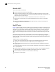
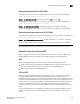
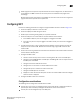
FIGURE 90 MCT architecture
MCT components
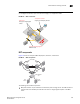
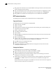
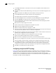
Figure 91 shows an example of MCT deployment, functions, and features.
FIGURE 91 MCT components
The following are the MCT components:
• MCT peer switches - A pair of switches connected as peers through an ICL. The LAG interface is
spread across the two MCT peer switches and acts as a single logical endpoint to the MCT
client.
Standard Link Aggregation
IEEE 802.3ad
MCT Peers
Acting as a single logical
switch.
Transparent to MCT
Support for third-party devices
ICL
CCEP
CEP CEP
CCEP
LAG
Switch bridge ID:
300
End
stations
End
stations
Bridge ID:
100
Bridge ID:
200
C
l
u
s
t
e
r
:
A
B
C