
Hardware Reference Manual Owner's manual
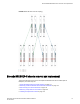

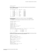
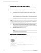

Stopping blade 1
Shutting down the blade....
Stopping blade 2
Shutting down the blade....
Stopping blade 8
Shutting down the blade....
Broadcast message from root (pts/1) Tue Jul 18 14:23:06 2008...
The system is going down for system halt NOW !!
DANGER
Disconnect the power cord from all power sources to completely remove power from the
device.
2. Power off the chassis by flipping all AC power switches to the off position. (The power supply status
LED should turn off.)
3. Remove the power cords from the power supplies and the power outlets.
4. Remove the chassis door.
5. Label the cables connected to all blades and record the connections.
6. Disconnect the cables from the SFP+ transceivers in the application and port blades and set them
aside. If you have mSFP transceivers in FC8-64 port blades, or QSFP transceivers in FC16-64 port
blades, remove the transceivers and cables together and set them aside. The SFP+ transceivers
can be left in the port blades or removed.
7. Disconnect all cables from the control processor and core switch blades.
8. Disconnect any ICL or QSFP cables.
Removing components from the chassis
Follow electrostatic discharge (ESD) precautions. Wear a wrist grounding strap connected to chassis
ground (if the Brocade DCX 8510-8is plugged in) or a bench ground.
DANGER
For safety reasons, the ESD wrist strap should contain a series 1 megaohm resistor.
1. Remove the chassis door (Chassis door removal and replacement on page 74) if not already done.
2. Remove the cable management comb (Cable management comb removal and replacement on
page 75).
3. Remove the port blades or filler panels (Port, application, and encryption blade removal and
replacement on page 76 and Blade filler panel removal and replacement on page 80).
4. Remove the core switch blades (CR16-8) (Core switch blade (CR16-8) removal and replacement on
page 90).
5. Remove the control processor blades (CP8) (Control processor blade (CP8) removal and
replacement on page 82).
6. Remove the power supplies or filler panels (Power supply removal and replacement on page 93).
7. Remove the blower assemblies (Blower assembly removal and replacement on page 96).
8. Remove the WWN bezel (logo plate) and WWN cards (GUID-91E4686C-E9CA-482D-92BC-
E1B523E0577F).
Installing the replacement chassis
Complete the following steps to install the replacement chassis.
Removing components from the chassis
116 Brocade DCX 8510-8 Backbone Hardware Reference Manual
53-1002180-07