
Hardware Reference Manual Owner's manual
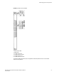
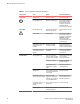
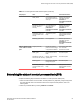
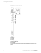
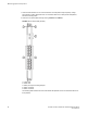
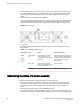
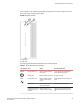
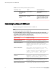

FIGURE 14 Control processor blade (CP8)
1. Power LED
2. Status LED
3. USB LED
4. USB port
5. Console port (Serial)
6. Ethernet port (Mgmt IP)
7. Ethernet port (Service IP)
8. Active CP LED
The following table describes the CP blade LED patterns and the recommended actions for those
patterns.
Monitoring System Components
64 Brocade DCX 8510-8 Backbone Hardware Reference Manual
53-1002180-07