
Hardware Reference Manual Owner's manual
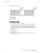
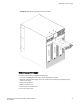

7. Verify that the power LED on the power supply displays a steady green light.
8. If you are installing two new power supplies in a DCX or DCX 8510-8 chassis to bring the total of
power supplies up to four, you should change the switchstatus policy settings for power supplies to
the following in order to enable the call home feature if one power supply goes down:
switch.status.policy.PowerSupplies.down = 1
switch.status.policy.PowerSupplies.marginal = 0
For more details on executing the switchStatusPolicyShow and switchStatusPolicySet
commands, refer to the Fabric OS Command Reference.
Blower assembly removal and replacement
Use this procedure to remove and replace a blower assembly.
NOTE
The Brocade DCX 8510-8 can continue operating during the replacement if the other two blower
assemblies are operating. To ensure continuous adequate cooling, maintain three operating blower
assemblies at all times except for the brief period when replacing a blower assembly.
Time and items required
The replacement procedure for each blower assembly takes less than 5 minutes. The following items
are required for the blower assembly replacement:
• Replacement blower assembly
• #2 Phillips screwdriver
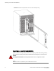
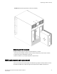
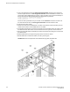
Removing a blower assembly
Complete the following steps to remove a blower assembly from the chassis.
1. Before removing a blower assembly, verify that the other blower assemblies are functioning
correctly. The power LEDs should be steady green.
2. Use the screwdriver to loosen the captive screws at the top and bottom of the blower assembly.
3. Grasp the handle and pull, sliding the blower assembly from the chassis and supporting the blower
assembly from beneath as you remove it.
Blower assembly removal and replacement
96 Brocade DCX 8510-8 Backbone Hardware Reference Manual
53-1002180-07