
Administrators Guide (Supporting Fabric OS v7.3.0) User Manual


cannot communicate with each other because they are in different fabrics, even though they are both
connected to the same physical chassis.
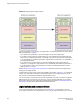
You can also connect other switches to logical switches. In Figure 22 , P6 is an E_Port that forms an
inter-switch link (ISL) between logical switch 4 and the non-Virtual Fabrics switch. Logical switch 4 is the
only logical switch that can communicate with the non-Virtual Fabrics switch and D2, because the other
logical switches are in different fabrics.
FIGURE 22 Logical switches connected to devices and non-Virtual Fabrics switch
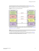
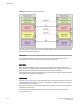
Figure 23 shows a logical representation of the physical chassis and devices in Figure 22 . As shown in
Figure 23 , the devices are isolated into separate fabrics.
FIGURE 23 Logical switches in a single chassis belong to separate fabrics
Managing Virtual Fabrics
Fabric OS Administrators Guide 273
53-1003130-01