
Administrators Guide (Supporting Fabric OS v7.3.0) User Manual

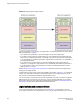


Think of the logical switches as being connected with logical ISLs, as shown in Figure 27 . In this
diagram, the logical ISLs are not connected to ports because they are not physical cables. They are a
logical representation of the switch connections that are allowed by the XISL.
FIGURE 27 Logical ISLs connecting logical switches
To use the XISL, the logical switches must be configured to allow XISL use. By default, they are
configured to do so; you can change this setting, however, using the procedure described in Configuring
a logical switch for XISL use on page 293.
NOTE
It is a good practice to configure at least two XISLs, for redundancy.
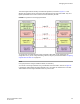
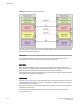
You can also connect logical switches using a combination of ISLs and XISLs, as shown in Figure 28 .
In this diagram, traffic between the logical switches in FID 1 can travel over either the ISL or the XISL.
Traffic between the other logical switches travels only over the XISL.
Managing Virtual Fabrics
Fabric OS Administrators Guide 277
53-1003130-01