
Administrators Guide (Supporting Fabric OS v7.3.0) User Manual
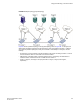
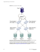
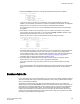
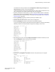
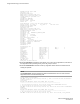

FIGURE 86 Sample topology (physical topology)
Figure 87 shows a phantom topology for the physical topology shown in Figure 86 . In this figure, the
dashed lines and shapes represent the phantom topology from the perspective of Fabric 1. Fabrics 2
and 3 also see phantom topologies, but they are not shown in this example. In this figure, note the
following:
• Front domain 1 and Front domain 2 are front domains for EX_Ports connecting to Fabric 1. There is
one front domain for each FC router that is connected to Fabric 1.
• Xlate domain 1 and Xlate domain 2 represent Fabrics 2 and 3, respectively. No xlate domain is
created for Fabric 4 because there are no LSAN devices in Fabric 4.
• Target 1’, Target 2’, and Target 3’ are proxy devices for Target 1, Target 2, and Target 3,
respectively.
Using FC-FC Routing to Connect Fabrics
Fabric OS Administrators Guide 541
53-1003130-01