
Hardware Installation Guide Owner's manual

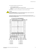
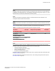


Switch fabric modules on page 27 shows an FSX 800 and FSX 1600 switch fabric module front panel.
FIGURE 7 FSX 800 and FSX 1600 switch fabric module front panel
Switch fabric module LEDs
The front panel provides status information through the LEDs listed in the table below.
Switch fabric module LEDsTABLE 6
LED Description and Position State Meaning
Pwr Top LED On (Green) The module is receiving power.
Off The module is not receiving power.
Active Bottom LED On (Green) The module is functioning properly.
Off The module is not functioning properly.
Interface modules
This section describes interface modules for the FastIron X Series chassis devices. The following
installation rules apply:
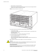
• In the FSX 800 device, you can install up to eight single slot and four double interface modules in
the slots shown in FSX 800 chassis on page 19.
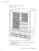
• In the FSX 1600 device, you can install up to 16 single slot and eight double slot interface
modules in the slots shown in FSX 1600 chassis on page 21.
NOTE
You cannot mix Second Generation and Third Generation modules in the same device.
The table below lists the supported interface modules for each FastIron X Series chassis device type.
Interface modules TABLE 7
Interface Module Part Number FSX 800 FSX 1600
Second Generation Interface Modules
24-port Gigabit Ethernet copper without PoE SX-FI624C X X
24-port Gigabit Ethernet copper with PoE SX-FI624P X X
Switch fabric module LEDs
28 Brocade FastIron SX Series Chassis Hardware Installation Guide
53-1003092-01