
Hardware Installation Guide Owner's manual

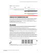
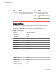

The copper ports provide status information using the LEDs described in the table below.
LEDs for 10/100/1000 copper ports TABLE 9
LED Position State Meaning
Link or Activity Square LED located at upper left corner of to port
(for top port)
Square LED located at upper right corner of top
port (for bottom port)
On (Green) A link is established with the
remote port.
Blinking The port is transmitting and
receiving traffic.
Off No link exists with the
remote port.
PoE (if applicable) Round LED located beneath the ports. The first
(left-most) LED is for port 1, the second LED is for
port 2, the third LED is for port 3, etc.
On (Green) The port is enabled, a
power-consuming device
has been detected, and the
module is supplying power to
the device.
Off The port is not providing in-
line power.
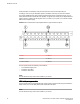
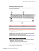
Third Generation 24-port Gigabit Ethernet copper module with PoE+
The 24-port Gigabit Ethernet copper interface module with PoE+ supports both IPv4 and IPv6. The
figure below shows the front panel of the IPv4 and IPv6 24-port Gigabit Ethernet copper interface
module with PoE+. The module requires Ironware 7.3 or later for FastIron series.
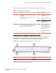
FIGURE 10 24-port Gigabit Ethernet copper module with PoE+ front panel
1. Port 1
13. Port 13
2. Port 2 14. Port 14
The front panel includes the following control features:
Third Generation 24-port Gigabit Ethernet copper module with PoE+
Brocade FastIron SX Series Chassis Hardware Installation Guide 33
53-1003092-01