
Hardware Installation Guide Owner's manual

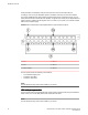
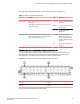
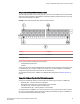
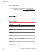

LEDs for 10 Gbps ports TABLE 13
LED Position State Meaning
Link or Activity Triangle-shaped LEDs point either upwards
or downwards towards the port it indicates
ON (Green) The port is connected, a link is
established with the remote port.
Blinking The port is transmitting or receiving
traffic.
OFF The port is not connected, no link
exists with the remote port
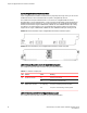
Network interfaces
The table below lists the network interfaces supported on FastIron X Series chassis devices. For
network interface and cabling specifications, refer to Cable specifications on page 160.
The output of the show media command displays the type of media installed in the ports.
Network interfaces TABLE 14
Interface Show Media Description
1000Base-BX-D M-GBXD
1000Base-BX-U M-GBXU
1000Base-CWDM Cxxxx (xxx denotes wavelength, for example, C1550
1000Base-LHA M-LHA
1000Base-LHB M-LHB
1000Base-LX M-LX
1000Base-SX M-SX
1000Base-SX2 M-XR or M-SX2
1000Base-T M-C
100Base-BX M-FBXD or M-FBXU
100Base-FX M-FX, M-FXB1, or M-FXB2
100Base-FX-IR M-FX-IR
100Base-FX-LR M-FX-LR
100Base-FX-SR M-FX-SR
100Base-TX (copper only) M-TX
Network interfaces
38 Brocade FastIron SX Series Chassis Hardware Installation Guide
53-1003092-01