
Hardware Installation Guide Manual


50 Brocade FastIron WS Hardware Installation Guide
53-1002498-02
Hardware specifications for FastIron WS models
5
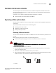
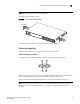
FIGURE 30 Console port pin assignments showing cable connection options to a terminal or PC
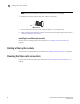
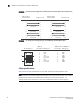
FIGURE 31 Pin assignment and signalling for 10/100BaseTX and 1000BaseT ports
Cable specifications
Table 22 lists the cable specifications for the cables used with the 10/100 Ethernet ports.
NOTE
Cable installation and network configuration will affect overall transmission capability. The numbers
provided below represent the accepted recommendations of the various standards. For
network-specific recommendations, consult your local Brocade reseller or system engineer.
1
2
3
4
5
6
7
8
9
1
2
3
4
5
6
7
8
9
1
2
3
4
5
6
7
8
9
8
3
2
20
7
6
4
5
22
Reserved
DB-9 to DB-9
Female Switch
DB-9 to DB-25
Female Switch
Reserved
Reserved
Reserved
Reserved
Reserved
Reserved
Reserved
Terminal or PC Terminal or PC
Pin Number
1
2
3
4
5
6
7
8
1
2
3
4
5
6
7
8
8
1
1
8
RD+
RD-
TD+
Not used
TD-
Not used
Not used
Not used
RD+
RD-
TD+
CMT
TD-
CMT
CMT
CMT
Pin Assignment MDI-X ports MDI-X ports
10BaseT
Pin Number
100BaseTX and 1000BaseT