53-1003197-01 27 June 2014 FC16-64 Port Blade QuickStart Guide Supporting Brocade DCX 8510-4 and DCX 8510-8 with Fabric OS 7.3.
© 2014, Brocade Communications Systems, Inc. All Rights Reserved. Brocade, the B-wing symbol, Brocade Assurance, ADX, AnyIO, DCX, Fabric OS, FastIron, HyperEdge, ICX, MLX, MyBrocade, NetIron, OpenScript, VCS, VDX, and Vyatta are registered trademarks, and The Effortless Network and the On-Demand Data Center are trademarks of Brocade Communications Systems, Inc., in the United States and in other countries. Other brands and product names mentioned may be trademarks of others.
Contents FC16-64 Overview.....................................................................................................................3 FC16-64 port blade........................................................................................... 3 QSFP transceiver..............................................................................................4 Qualified transceivers for the FC16-64 port blade and the core blades............4 Cable types supported on the FC16-64 port blade..............
2 FC16-64 Port Blade QuickStart Guide 53-1003197-01
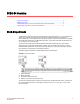
FC16-64 Overview ● FC16-64 port blade........................................................................................................... 3 ● QSFP transceiver..............................................................................................................4 ● Qualified transceivers for the FC16-64 port blade and the core blades............................4 ● Cable types supported on the FC16-64 port blade...........................................................
QSFP transceiver QSFP transceiver The FC16-64 port blade supports only Quad-SFP (QSFP) ports where a single MTP connector supports up to four channels or ports. Thus, QSFP allows for simplified cable management and, at the same time, supports high density SAN solutions. The QSFP transceivers differ from standard SFP+ or mSFP transceivers. Cables with MTP/MPO connectors are required to use the QSFP transceivers.
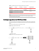
Cable types supported on the FC16-64 port blade TABLE 1 Qualified transceivers for FC16-64 port blade and the core blades Brocade part number Part type Cable length Port speeds Supported blades 57-1000294-01 QSFP transceiver 100 m OM4 Auto-negotiable 4-, 8-, and 16-Gbps FC16-64 57-1000267-01 QSFP transceiver 100 m OM4 Only fixed 16-Gbps CR16-4/8 57-0000090-01 QSFP transceiver 50 m OM3 NOTE The QSFP transceivers supported on FC16-64 port blade are not interchangeable with QSFP transceivers
FC16-64 Overview With the support for breakout cables, each port can be in a different mode. Inside the single physical QSFP port, individual ports can be configured as an E_Port, F_Port or EX_Port. Also, each internal port inside a single physical QSFP can be part of different Logical Switches. With the support for breakout cables, trunking can be enabled on ports in a QSFP port group, with ports connected through breakout cables at the other end.
Installing the FC16-64 ● Before you begin............................................................................................................... 7 ● ESD precautions............................................................................................................... 7 ● Time required for installation tasks................................................................................... 7 ● Items required......................................................................................
Installing the blade in the chassis • • • • • • FC16-64 port blades (as many as ordered) Sufficient number of QSFP transceivers to fill the FC16-64 blades. Velcro® strips QSFP to QSFP cables (if necessary, to be used as inter-switch links (ISLs) or MTP patch panels) QSFP-LC patch cables (if necessary, to be used with LC patch panels) Phillips screwdriver Installing the blade in the chassis Complete the following steps to install the port blade in the chassis. 1.
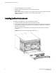
Attaching cables to the blade For an example of how a blade needs to be oriented in 8510-8 chassis, refer to the following illustration. FIGURE 6 Insertion of the FC16-64 port blade in DCX 8510-8 3. Adjust the ejectors to the open position by rotating them toward the center of the blade, align the flat side of the blade inside the upper and lower rail guides in the slot, and slide the blade into the slot until it is firmly seated. 4.
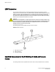
Bundling and routing cables 1. Remove the protective caps on the QSFP transceiver and the QSFP connector on the cable. 2. If the transceiver was not pre-installed, grasp the bail of the QSFP transceiver and push the transceiver into the port until it is firmly seated and the latching mechanism clicks. The transceiver is keyed to fit into the port with the correct orientation. If a transceiver does not slide in easily, ensure that it is correctly oriented.
Installing the FC16-64 For the DCX 8510-8, the cable management combs are mounted to the bottom of the chassis. You need to route the cables towards the bottom and then bundle them together for each FC16-64 port blade. FIGURE 8 Cable routing in DCX 8510-8 For the DCX 8510-4, the cable management fingers are mounted to the sides of the chassis, making the task of bundling and routing the cables in two directions.
Attaching cables to the patch panels the left of a FC16-64 port blade to the left cable management finger, and those in the right to the right cable management finger. FIGURE 9 Cable routing in DCX 8510-4 Attaching cables to the patch panels You can use three types of patch panels to connect FC16-64 port blades to other devices.
Installing the FC16-64 1. Install the patch panel in the rack. See the directions accompanying the patch panel for detailed mounting instructions. Leave a one rack unit gap between the bottom of a DCX 8510-8 chassis and the first patch panel to allow for bending of the optical cables after they pass through the cable management comb. If you mount the patch panels above the chassis, leave a one rack unit gap below a chassis for bending the cables after they pass through the cable management comb. 2.
Attaching cables to the patch panels 14 FC16-64 Port Blade QuickStart Guide 53-1003197-01
Additional documentation For more information, refer to the following documents: • • • • DCX 8510-8 Backbone Hardware Reference Manual DCX 8510-8 Backbone QuickStart Guide DCX 8510-4 Backbone Hardware Reference Manual DCX 8510-4 Backbone QuickStart Guide FC16-64 Port Blade QuickStart Guide 53-1003197-01 15
Additional documentation 16 FC16-64 Port Blade QuickStart Guide 53-1003197-01