
User Manual

Chapter 4. Cabling the switch module and the SFP+ module 21
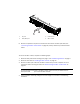
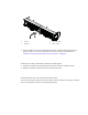
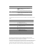
FIGURE 1 0 Fiber optic cable insertion
3. Check the LEDs on the switch module. When the switch module is operating correctly, the
green link LED is lit. For information about the status of the switch module LEDs, see ,
“Chapter 5. Information panels, LEDs, and external ports,” on page 23.
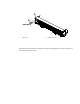
Disconnecting the SFP+ module cable
To disconnect the SFP+ module cable, complete the following steps:
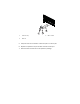
1. Squeeze the release tabs and gently pull the fiber optic cable from the SFP+ module.
2. Replace the protective caps on the ends of the fiber optic cable.
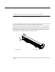
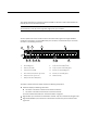
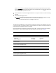
Connecting the RJ-45 Ethernet cable
The RJ-45 Ethernet cable can be connected to the RJ-45 port.
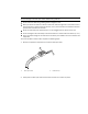
To connect the RJ-45 connector to the switch module, push the connector into the port connector
until it clicks into place, as shown in the following illustration.
1 FC ports 3 Fiber optic cable
2 CEE ports 4 SFP+ module
2
1
3
4