
Hardware Installation Guide Manual
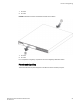


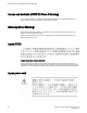

1. Air inflow
2. Air outlet
FIGURE 51 Brocade FCX 624-I and Brocade FCX 648-I device airflow
1. Air inflow
2. Air outlet
For a complete list of regulatory compliances refer to the Regulatory Statements section.
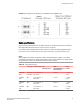
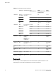
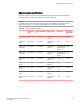
Pinouts and signalling
This section describes the pinout diagrams for the DB-9 connector and RJ45 port jacks.
Pinouts and signalling
Brocade FCX Series Hardware Installation Guide 89
53-1003077-01