53-1001274-06 16 November 2012 ® Fixed Rack Mount Kit Installation Procedure Supporting Brocade 300, 5100, 5300, 6520, 7800, 8000, Encryption Switch, VA-40FC, VDX 6710-54, VDX 6720-24, VDX 6720-60, VDX 6730-32, and VDX 6730-76 53-1001274-06 *53-1001274-06*
Copyright © 2003-2012 Brocade Communications Systems, Inc. All Rights Reserved. Brocade, Brocade Assurance, the B-wing symbol, BigIron, DCX, Fabric OS, FastIron, MLX, NetIron, SAN Health, ServerIron, TurboIron, VCS, and VDX are registered trademarks, and AnyIO, Brocade One, CloudPlex, Effortless Networking, ICX, NET Health, OpenScript, and The Effortless Network are trademarks of Brocade Communications Systems, Inc., in the United States and/or in other countries.
Brocade Communications Systems, Incorporated Corporate and Latin American Headquarters Brocade Communications Systems, Inc. 130 Holger Way San Jose, CA 95134 Tel: 1-408-333-8000 Fax: 1-408-333-8101 E-mail: info@brocade.com Asia-Pacific Headquarters Brocade Communications Systems China HK, Ltd. No. 1 Guanghua Road Chao Yang District Units 2718 and 2818 Beijing 100020, China Tel: +8610 6588 8888 Fax: +8610 6588 9999 E-mail: china-info@brocade.
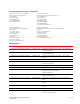
Title Publication number Summary of changes Date Fixed Rack Mount Kit Installation Procedure 53-1001274-05 Added support for VDX 6710 and VDX 6730 models. September 2011 Fixed Rack Mount Kit Installation Procedure 53-1001274-06 Added support for Brocade 6520 model.
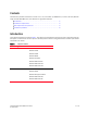
Contents This document provides instructions to install a 1U, 1.5U, or 2U switch (or SAN Router) in a 19-in. (48.3 cm) EIA rack using the Fixed Rack Mount Kit. The document is organized as follows: • Introduction. . . . . . . . . . . . . . . . . . . . . . . . . . . . . . . . . . . . . . . . . . . . . . . . . . . . • Installation requirements. . . . . . . . . . . . . . . . . . . . . . . . . . . . . . . . . . . . . . . . . • Tool requirements and parts list . . . . . . . . . . . . . . . . . . . . . . . . . .
Installation requirements Allow 15 to 30 minutes to complete this procedure. Note the following requirements to ensure correct installation and operation: • Provide space in a 19-in. (48.3 cm) EIA rack, as required for the switch type, with a minimum distance of 28.25 in. (71.76 cm) and a maximum distance of 29.88 in. (75.90 cm) between the front and back posts. • Verify that the additional weight of the switch does not exceed the rack weight limits.
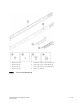
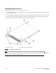
1 Bracket, front right 5 Screw, 8-32 x 5/16-in., panhead Phillips (12) 2 Bracket, front left 6 Screw, 6-32 x 1/4-in., flathead Phillips (8) 3 Bracket, rear left 7 Screw, 10-32 x 5/8-in.
Installation procedure ATTENTION The switch must be turned off and disconnected from the fabric during this procedure. NOTE Although this document describes how to install single-height (1U) and double-height (2U) switches, the illustrations show a single-height switch as a typical installation.
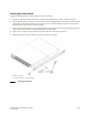
Attaching the front brackets Complete the following steps to attach the front brackets to the switch. 1. Position the right front bracket with the flat side against the right side of the switch, as shown in Figure 2. 2. Insert two 8-32 x 5/16-in. screws into one of the pairs of vertically aligned holes in the bracket and then into the pair of holes on the side of the switch. To install the switch in a recessed position in the rack, use the bracket holes that are set back from the end of the bracket. 3.
Installing the switch in the rack Complete the following steps to install the switch in the rack. 1. Position the switch in the rack, as shown in Figure 3, providing temporary support under the switch until the rail kit is secured to the rack. 2. Attach the right front bracket to the right front rack post using two 10-32 x 5/8-in. screws and two retainer nuts. 3. Attach the left front bracket to the left front rack post using two 10-32 x 5/8-in. screws and two retainer nuts. 4.
Attaching the rear brackets to the front brackets Complete the following steps to attach the rear brackets to the front brackets. 1. Position the right rear bracket inside the right front bracket, as shown in Figure 4. 2. Attach the brackets using four 6-32 x 1/4-in. screws. 3. Repeat step 1 and step 2 to attach the left rear bracket to the left front bracket. 4. Adjust the brackets to the rack depth and tighten all the 6-32 x 1/4-in. screws to a torque of 9 in-lbs (10 cm-kgs).
Attaching the rear brackets to the rack posts Complete the following steps to attach the rear brackets to the rack posts. 1. Attach the right rear bracket to the right rear rack post using two 10-32 x 5/8-in. screws and two retainer nuts, as shown in Figure 5. 2. Attach the left rear bracket to the left rear rack post using two 10-32 x 5/8-in. screws and two retainer nuts. 3. Tighten all the 10-32 x 5/8-in. screws to a torque of 25 in-lbs (29 cm-kgs).