‘ 53-1001273-07 22 July 2013 ® Mid-Mount Rack Kit (Switch) Installation Procedure Supporting Brocade 300, 5100, 5300, 6505, 6510, 6520, 7800, 8000, VA-40FC, VDX 6710-54, and VDX 6740 53-1001273-07 *53-1001273-07*
Copyright © 2006-2013, Brocade Communications Systems, Incorporated. All Rights Reserved. ADX, AnyIO, Brocade, Brocade Assurance, the B-wing symbol, DCX, Fabric OS, ICX, MLX, MyBrocade, OpenScript, VCS, VDX, and Vyatta are registered trademarks, and HyperEdge, The Effortless Network, and The On-Demand Data Center are trademarks of Brocade Communications Systems, Inc., in the United States and/or in other countries.
Document History Title Publication number Summary of changes Date Mid-Mount Rack Kit Installation Procedure 53-1000171-01 New document. February 2006 Mid-Mount Rack Kit (Switch) Installation Procedure 53-1000171-02 Updated for new switches, format, and template. June 2008 Mid-Mount Rack Kit (Switch) Installation Procedure 53-1001273-01 Added support for the Brocade 8000 Switch.
Contents This document provides instructions to install a 1U, 1.5U, or 2U switch (or SAN Router) in a telecommunications (Telco) rack using the Mid-Mount Rack Kit. The document is organized as follows: • Introduction . . . . . . . . . . . . . . . . . . . . . . . . . . . . . . . . . . . . . . . . . . . . . . . . . . . . • Installation requirements . . . . . . . . . . . . . . . . . . . . . . . . . . . . . . . . . . . . . . . . . • Tool requirements and parts list. . . . . . . . . . . . . . . . . . . . . . .
• Ensure that an electrical branch circuit with the following characteristics is available: - Required voltage and frequency as indicated in the hardware reference manual (200-240 VAC is always preferred). - Protection by a circuit breaker in accordance with local electrical codes. Supply circuit, line fusing, and wire size that conform to the electrical rating on the switch nameplate. Grounded outlet compatible with the power cord and installed by a licensed electrician.
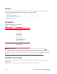
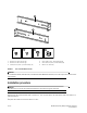
1 2 3 4 5 6 1 Bracket, front right and back left 4 Screw, 6-32 x 1/4-in., flathead Phillips (8) 2 Bracket, front left and back right 5 Screw, 10-32 x 5/8-in., panhead Phillips (8) 3 Screw, 8-32 x 5/16-in., panhead Phillips (12) 6 Retainer nut, 10-32 (8) FIGURE 1 Items in the Mid-Mount Rack Kit ATTENTION For the Brocade 6505, Brocade 6510, and Brocade 6520 Mid-Mount Rack Kit, there will only be front left and front right brackets.
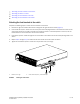
• • • • “Attaching the front brackets to the switch” “Attaching the switch to a rack” “Attaching the rear brackets to the rack” “Attaching the rear brackets to the switch” Attaching the front brackets to the switch Complete the following steps to attach the front brackets to the switch. 1. Position the right front bracket with the flat side against the right side of the switch (Figure 2). 2. Insert two 8-32 x 5/16-in.
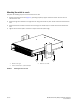
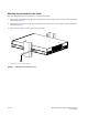
Attaching the switch to a rack Complete the following steps to install the switch in the rack. 1. Position the switch in the rack (Figure 3), providing temporary support under the switch until the rail kit is secured to the rack. 2. Attach the right front bracket to the right rack rail using three 10-32 x 5/8-in. screws and three 10-32 retainer nuts. 3. Attach the left front bracket to the left rack rail using three 10-32 x 5/8-in. screws and three 10-32 retainer nuts. 4. Tighten all the 10-32 x 5/8-in.
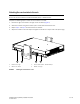
Attaching the rear brackets to the rack NOTE Do not use the rear brackets for the Brocade 6505, 6510, or 6520 switches. Complete the following steps to attach the rear brackets to the rack. 1. Position the right rear bracket in the right rear of the switch (Figure 4). 2. Attach the brackets using three 10-32 x 5/8-in. screws and 10-32 retainer nuts. 3. Repeat step 1 and step 2 to attach the left rear bracket. 4.
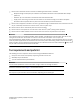
Attaching the rear brackets to the switch Complete the following steps to attach the rear brackets to the switch. 1. Align the right rear bracket to the right rear of the switch and use two 6-32 x 1/4-in. screws to attach the bracket to the switch (Figure 5). 2. Align the left rear bracket to the left rear of the switch and use two 6-32 x 1/4-in. screws to attach the bracket to the switch (Figure 5). 3. Tighten all the screws to a torque of 9 in-lbs (10 cm-kgs). 1 1 Screw, 6-32 x 1/4-in.