
Installation Procedure (Supporting 300, 5100, 5300, 6505, 6510, 6520, 7800, 8000, VA-40FC, VDX 6710-54, and VDX 6740) Owner manual


6 of 10 Mid-Mount Rack Kit (Switch) Installation Procedure
53-1001273-07
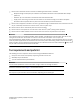
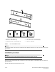
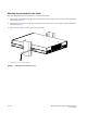
FIGURE 1 Items in the Mid-Mount Rack Kit
ATTENTION
For the Brocade 6505, Brocade 6510, and Brocade 6520 Mid-Mount Rack Kit, there will only be front left and front
right brackets.
Installation procedure
ATTENTION
The switch must be turned off and disconnected from the fabric during this procedure.
NOTE
Although this document describes how to install a 1U, 1.5U, and 2U switch, the illustrations show a 2U switch as a
typical installation.
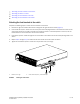
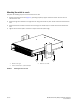
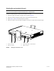
Complete these tasks to install the switch in a rack:
1 Bracket, front right and back left 4 Screw, 6-32 x 1/4-in., flathead Phillips (8)
2 Bracket, front left and back right 5 Screw, 10-32 x 5/8-in., panhead Phillips (8)
3 Screw, 8-32 x 5/16-in., panhead Phillips (12) 6 Retainer nut, 10-32 (8)
3
4
5
6
1
2