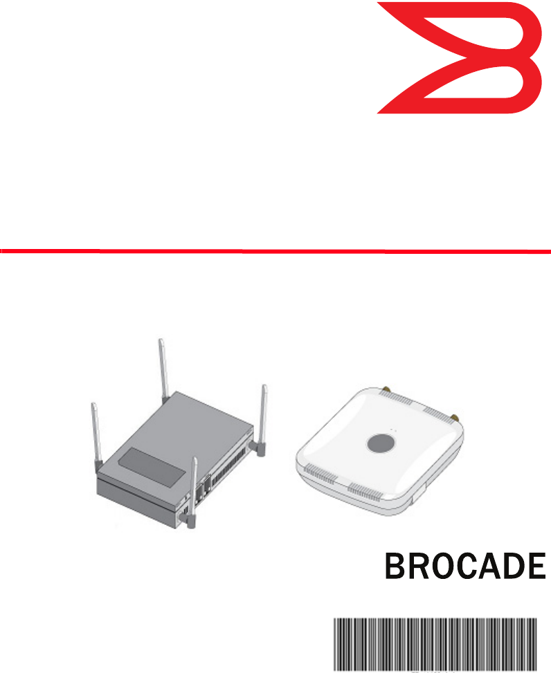
® Brocade Mobility 1220 Access Point Installation Guide 53-1002916-01
Copyright © 2013 Brocade Communications Systems, Inc. All Rights Reserved. ADX, AnyIO, Brocade, Brocade Assurance, the B-wing symbol, DCX, Fabric OS, ICX, MLX, MyBrocade, OpenScript, VCS, VDX, and Vyatta are registered trademarks, and HyperEdge, The Effortless Network, and The On-Demand Data Center are trademarks of Brocade Communications Systems, Inc., in the United States and/or in other countries. Other brands, products, or service names mentioned may be trademarks of their respective owners.
Contents Chapter 1 Introduction Document conventions . . . . . . . . . . . . . . . . . . . . . . . . . . . . . . 2 Warnings . . . . . . . . . . . . . . . . . . . . . . . . . . . . . . . . . . . . . . . . . . 2 Site preparation . . . . . . . . . . . . . . . . . . . . . . . . . . . . . . . . . . . . 3 Package contents . . . . . . . . . . . . . . . . . . . . . . . . . . . . . . . . . . . External antenna model package contents. . . . . . . . . . . Internal antenna model package contents . . . . . . . . . .
External antenna model suspended ceiling t-bar mount. . . . 17 Suspended ceiling t-bar mount procedure using mounting kit . . . . . . . . . . . . . . . . . . . . . . . . . . . . . . 17 Suspended ceiling T-bar mount procedure using ceiling mount hardware . . . . . . . . . . . . . . . . . . . . . 18 External antenna suspended ceiling tile (Plenum) mount . . . . . . . . . . . . . . . . . . . . . . . . . . . . . . . . . . . . . . . . . . . . 20 Suspended ceiling mount hardware . . . . . . . . . . . . . . . .
Health and Safety Recommendations . . . . . . . . . . . . . . . . . . Warnings for Use of Wireless Devices . . . . . . . . . . . . . . . Potetially Hazerdous Atmospheres Fixed Installations . . . . . . . . . . . . . . . . . . . . . . . . . . . . . . . Safety in Hospitals . . . . . . . . . . . . . . . . . . . . . . . . . . . . . . Pacemakers. . . . . . . . . . . . . . . . . . . . . . . . . . . . . . . . . . . . Other Medical Devices . . . . . . . . . . . . . . . . . . . . . . . . . . .
Chapter Introduction 1 The Brocade Mobility™ 1220 Access Point, a component of the Brocade wireless controller system, links wireless 802.11a/b/g/n devices to the controller, enabling the growth of your wireless network with a cost effective alternative to standard access points. The Mobility 1220 Access Point provides multiple deployment options. The Mobility 1220 Access Point receives all power and transfers data through the same CAT-5 or better Ethernet cable. An 802.
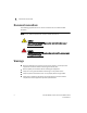
1 Document conventions Document conventions The following graphical alerts are used in this document to indicate notable situations NOTE Tips, hints, or special requirements that you should take note of. CAUTION Care is required. Disregarding a caution can result in data loss or equipment malfunction. DANGER Indicates a condition or procedure that could result in personal injury or equipment damage.
Site preparation 1 Site preparation • Consult your site survey and network analysis reports to determine specific equipment placement, power drops, and so on. • • • • • Assign installation responsibility to the appropriate personnel. Identify and document where all installed components are located. Ensure adequate, dust-free ventilation to all installed equipment. Identify and prepare Ethernet and console port connections.
1 Package contents Features • 2 RJ-45 connectors, one for 10/100/1000 Ethernet and the other for the serial/console connector • LED indicators • Slots for wall mounting • Clips for mounting on a suspended ceiling T-bar (internal antenna model only) with separately orderable accessories • Lock port for Kensington® style Security Lock The Mobility 1220 Access Point has one RJ-45 connector supporting an 10/100/1000 Ethernet port and accepts 802.3af-compliant power from an external source.
Package contents 1 Contacting Brocade When contacting Brocade support, please provide the following information: • Serial number of the unit • Model number or product name • Software version Customer Support Web Site Brocade Support Central Web site, located at www.brocade.com/support provides information and online assistance including developer tools, software downloads, product manuals and online repair requests. Downloads http://www.brocade.com/support/ Manuals http://www.brocade.
1 Package contents Warranty coverage Contact Brocade Communications Systems using any of the methods listed above for information about the standard and extended warranties.
Chapter Hardware Installation 2 Installation instructions The Mobility 1220 Access Point mounts either on a wall (with customer supplied M4 x 25 pan head screws and wall anchor - or equivalent) or on a suspended ceiling T-bar. If deploying an external antenna model Mobility 1220 on a suspended ceiling T-bar, access point mounting kit (Part No. KT-135628-01) is required. A Mobility 1220 is not designed for mounting on a desk. To prepare for the installation: 1.
2 Precautions 4. Connect a CAT-5 or better Ethernet cable to a compatible 802.3af power source and run the cable to the installation site. Ensure there is sufficient slack on the cable to perform the installation steps. NOTE When operating in a Gigabit Ethernet environment, CAT-5e or CAT-6 cable is recommended for Gigabit operation.
Integrated antenna model wall mount instructions 2 To maximize the access point’s radio coverage area, Brocade recommends conducting a site survey to define and document radio interference obstacles before installing the access point. Integrated antenna model wall mount instructions Wall mounting requires hanging the Mobility 1220 Access Point along its width or length using the two slots on the bottom of the unit.
2 Integrated antenna model wall mount instructions Wall mount procedure 10 Brocade Mobility 1220 Access Point Installation Guide 53-1002916-01
Integrated antenna model wall mount instructions 2 1. Orient the case on the wall by its width or length. CAUTION To ensure proper operation of a Mobility 1220 Access Point, ensure it is mounted in the correct orientation as shown above. 2. Mark two points (for drill holes) 4.08 inches (103.7 mm) apart on a horizontal line. 3. At each point, drill a hole in the wall, insert an anchor, screw into the anchor the wall mounting screw and stop when there is 1mm between the screw head and the wall.
2 Integrated antenna model wall mount instructions 4. If required, install and attach a Kensington security cable (customer supplied) to the unit’s lock port. 5. Attach an Ethernet cable from the access point to a controller or Ethernet switch with an 802.3af-compatible power source or use the PWRS-14000-148R power supply to supply power to the Mobility 1220 Access Point (once fully cabled). 6. Place the middle of each of the case’s mount slots over the screw heads. 7.
Integrated antenna model suspended ceiling t-bar mount 2 Integrated antenna model suspended ceiling t-bar mount Ceiling mount requires holding the Mobility 1220 Access Point up against a T-bar of a suspended ceiling grid and twisting the case onto the T-bar. Suspended ceiling T-bar mount procedure 1. If required, install and attach a Kensington security cable (customer supplied) to the unit’s lock port. 2. Attach an Ethernet cable from the access point to a device with an 802.
2 External antenna model wall mount instructions 6. Push the back of the case onto the bottom of the T-bar. 7. Rotate the case 45 degrees counter-clockwise. The clips click as they fasten to the T-bar. 8. Verify the unit has power by observing the LEDs. CAUTION If not using a 802.3af capable device to power the Mobility 1220 Access Point, ensure only the Mobility 1220 Access Point’s designated power supply (PWRS-14000-148R) is used to supply power to the access point.
External antenna model wall mount instructions 2 Wall mount procedure - new installation This section describes a new Mobility 1220 Access Point installation with no previous access point existing on the intended wall surface. 1. Attach the two provided mounting ears (using four ear mounting screws) to the two narrow ens of the Mobility 1220 Access Point. Align the ears using the built in ear alignment pin on the access point housing. Torque the screws to 6 lb-in. 2.
2 External antenna model wall mount instructions 5. Place the access point on the anchor. Insert screws through the access point’s mounting ears and into the anchor. 6. If required, install and attach a Kensington security cable (customer supplied) to the unit’s lock port. 7. Attach an Ethernet cable from the access point to a device with an 802.3af-compatible power source or use the PWRS-14000-148R power supply to supply power to the Mobility 1220 Access Point (once fully cabled). 8.
External antenna model suspended ceiling t-bar mount 2 External antenna model suspended ceiling t-bar mount Ceiling mount requires holding the Mobility 1220 Access Point up against a T-bar of a suspended ceiling grid and twisting the case onto the T-bar. If deploying an external antenna model Mobility 1220 Access Point on a ceiling T-Bar, access point mounting kit (Part No. KT-135628-01) or ceiling mount hardware (SCT-2) is required.
2 External antenna model suspended ceiling t-bar mount the unit and void the product warranty. Do not actually connect to the power source until the cabling portion of the installation is complete. Suspended ceiling T-bar mount procedure - using ceiling mount hardware The following installation uses the access point ceiling mounting kit (Part No. SCT-2) to deploy the access point on a ceiling T-Bar. 1.
External antenna model suspended ceiling t-bar mount 2 5. Attach an Ethernet cable from the access point to a device with an 802.3af compatible power source or use the PWRS-14000-148R power supply to supply power to the Mobility 1220 Access Point (once fully cabled). 6. Attach appropriate antennas to the connectors. 7. Verify the unit has power by observing the LEDs. CAUTION If not using an 802.
2 External antenna suspended ceiling tile (Plenum) mount External antenna suspended ceiling tile (Plenum) mount Ceiling mount requires placing the Mobility 1220 Access Point above suspended ceiling tile. NOTE Notes or warnings about suspended ceiling mounts apply to all installations where the unit is placed on suspended ceiling tile. CAUTION Brocade does not recommend mounting the Mobility 1220 Access Point directly to any suspended ceiling tile with a thickness less than 12.7mm (0.5in.
External antenna suspended ceiling tile (Plenum) mount 2 5. Bring the tile into the ceiling space 6. Attach an Ethernet cable from the access point to a device with an 802.3af compatible power source or use the PWRS-14000-148R power supply to supply power to the Mobility 1220 Access Point (once fully cabled). 7. Verify the access point is receiving power by observing the LEDs. 8. Place the ceiling tile back in its frame. CAUTION If not using an 802.
2 Mobility 1220 Access Point external antenna model antenna options Mobility 1220 Access Point external antenna model antenna options Brocade supports two antenna suites for Mobility 1220 External Antenna models. One antenna suite supporting the 2.4 GHz band and another antenna suite supporting the 5 GHz band. Select an antenna model best suited to the intended operational environment of your access point.
Mobility 1220 Access Point external antenna model antenna options 2 The 2.
2 LED indicators LED indicators Both Integrated Antenna and External Antenna models have LED activity indicators on the front of the case. With the External Antenna models mounted above a ceiling, LEDs are at the center of an oval badge on the ceiling. The LEDs provide a status display indicating error conditions, transmission, and network activity for the 5 GHz 802.11a/n (amber) radio or the 2.4 GHz 802.11b/g/n (green) radio.
2 LED indicators Task 5 GHz Activity LED (Amber) 2.
Chapter Initial Access Point Configuration 3 Once the Access Point is installed and powered on, complete the following steps to get the device up and running by using the Initial Setup Wizard: 1. Attach an Ethernet cable from the Access Point to a device with an 802.3af compatible power source or use the PWRS-14000-148R power supply to supply power to the Mobility 1220 Access Point (once fully cabled).
Initial Access Point Configuration 3 2. Point the Web browser to the Mobility 1220 access point’s IP address (using https://). The following login screen displays. 3. Enter the default username admin in the Username field. 4. Enter the default password admin123 in the Password field. 5. Click the Login button to load the management interface. NOTE When logging in for the first time, you are prompted to change the password to enhance device security in subsequent logins.
3 Initial Access Point Configuration 6. Select the Start Wizard button to run the initial setup wizard. The setup wizard displays the first time the Mobility 1220 Access Point user interface is accessed in order to define the Access Point’s initial configuration. 7. 28 If this is the first time the management interface has been accessed, a dialogue displays to start the wizard.
Initial Access Point Configuration 3 The first page of the Initial AP Setup Wizard displays the Navigation Panel and Introduction for the configuration activities comprising the Access Point's initial setup. A green checkmark to the left of an item in the Navigation Panel defines the listed task as having its minimum required configuration parameters set correctly. A red X defines the task as still requiring at least one parameter be defined correctly.
3 Initial Access Point Configuration The Introduction screen displays a list of the basic configuration activities supported by the Initial Setup Wizard. 8. Select Save/Commit within each page to save the updates made to that page's configuration. Select Next to proceed to the next page listed in the Navigation Panel. Select Back to revert to the previous screen in the Navigation Panel without saving your updates.
Initial Access Point Configuration 3 9. Select Next. The Initial AP Setup Wizard displays the Access Point Type screen to define the Access Point's Standalone versus Virtual Controller AP functionality and the way the Access Point is adopted to a controller.
3 Initial Access Point Configuration 10. Select an Access Point Type from the following options: • Virtual Controller AP - When more than one Access Point is deployed, a single Access Point can function as a Virtual Controller AP. Up to 24 Access Points can be connected to, and managed by, a single Virtual Controller AP of the same Mobility 1220 Access Point model. • Standalone AP -Select this option to deploy this Access Point as an autonomous fat Access Point.
Initial Access Point Configuration 3 If you are using the static method, you will also need to define whether the Access Point receives an IP address using DHCP or if IP resources are provided statically.
3 Initial Access Point Configuration 12. Select Next. The Initial AP Setup Wizard displays the Access Point Mode screen to define the Access Point's routing or bridging mode functionality.
Initial Access Point Configuration 3 13. Select a Access Point Mode from the available options. • Router Mode - In Router Mode, the Access Point routes traffic between the local network (LAN) and the Internet or external network (WAN). Router mode is recommended in a deployment supported by just a single Access Point. • Bridge Mode - In Bridge Mode, the AP depends on an external router for routing LAN and WAN traffic.
3 Initial Access Point Configuration 14. Select Next. The Initial AP Setup Wizard displays the LAN Configuration screen to set the Access Point's LAN interface configuration.
Initial Access Point Configuration 3 15. Set the following DHCP and Static IP Address/Subnet information for the LAN interface: • Use DHCP - Select the checkbox to enable an automatic network address configuration using the Access Point’s DHCP server. • Static IP Address/Subnet - Enter an IP Address and a subnet for the Access Point's LAN interface. If Use DHCP is selected, this field is not available.
3 Initial Access Point Configuration 16. Select Next. The Initial AP Setup Wizard displays the WAN Configuration screen to set the Access Point's WAN interface configuration.
Initial Access Point Configuration 3 17. Set the following DHCP and Static IP Address/Subnet information for the WAN interface: • Use DHCP - Select the checkbox to enable an automatic network address configuration using the Access Point’s DHCP server. • Static IP Address/Subnet - Enter an IP Address/Subnet and gateway for the Access Point's WAN interface. These are required fields • The port connected to the WAN - Select the port used as the physical Access Point connection to the external network.
3 Initial Access Point Configuration 19. Set the following parameters for the radio: • Configure as a Data Radio - Select this option to dedicate this radio for WLAN client support in either the selected 2.4 or 5 GHz radio band. • Radio Frequency Band - Select either the 2.4 GHz or 5.0 GHz radio band to use with the radio when selected as a Data Radio. The selected band is used for WLAN client support. Considers selecting one radio for 2.
Initial Access Point Configuration 3 20. Select Next. The Initial AP Setup Wizard displays the Wireless LAN Setting screen to define network address and security settings for two WLAN configurations available to the Access Point as part of the Initial Setup Wizard. Once the Access Point has an initial configuration defined, numerous additional WLAN configurations can be set.
3 Initial Access Point Configuration 21. Set the following parameters for each of the two WLAN configurations available as part of this Initial AP Setup Wizard: • SSID - Enter or modify the Services Set Identification (SSID) associated with the WLAN. The WLAN name is auto-generated using the SSID until changed by the user. The maximum number of characters is 32. Do not use < > | “ & \ ? , This is a required parameter for each WLAN.
Initial Access Point Configuration 3 NOTE If you are using the Access Point’s onboard RADIUS server, an additional RADIUS Server Configuration screen displays within the Navigation Panel on the left-hand side of the screen. Use this screen to create user accounts validated when the Access Point authenticates client connection requests to the onboard RADIUS server. 22. Select Next.
3 Initial Access Point Configuration 23. Refer to the Username, Password, Description, and Actions columns to review credentials of existing RADIUS Server user accounts. Add new accounts or edit the properties of existing accounts as updates are required. 24. Refer to the Add On-Board RADIUS Server Users field to set the following parameters for a user account: • Username - If you are adding a new user account, create a username up to X characters in length.
Initial Access Point Configuration 3 26. Select Next. The Initial AP Setup Wizard displays the Country/Date/Time screen to set device deployment, administrative contact and system time information. The system time can either be set manually or be supplied by a dedicated Network Time Protocol (NTP) resource.
3 Initial Access Point Configuration 27. Refer to the Country and Time Zone field to set the following device deployment information: • Location - Define the location of the Access Point. The Location parameter acts as a reminder of where the AP is deployed within the Brocade managed wireless network. • Contact - Specify the contact information for the administrator. The credentials provided should accurately reflect the individual responding to service queries.
Initial Access Point Configuration 3 If a screen shows settings not intended as part of the initial configuration, the screen can be selected from within the Navigation Panel and its settings modified accordingly. 33. If the configuration displays as intended, select the Save/Commit button to implement these settings to the Access Point’s configuration.
Chapter 4 Specifications Mobility 1220 integrated antenna model electrical characteristics A Mobility 1220 integrated antenna Access Point has the following electrical characteristics: Operating Current & Voltage 12VDC, 1A (accessory power connector) 48V,0.25A (PoE connector) Mobility 1220 integrated antenna model physical characteristics A Mobility 1220 integrated antenna Access Point has the following physical characteristics: Dimensions 9.38 inches x 7.5 inches x 1.38 inches 23.82 cm x 19.
Mobility 1220 external antenna model electrical characteristics 4 Mobility 1220 external antenna model electrical characteristics A Mobility 1220 external antenna Access Point has the following electrical characteristics: Operating Current & Voltage 12VDC, 1A (accessory power connector) 48V,0.25A (PoE connector) Mobility 1220 external antenna model physical characteristics A Mobility 1220 external antenna Access Point has the following physical characteristics: Dimensions 7.88 inches x 5.00 inches x 1.
4 Radio characteristics Radio characteristics The Mobility 1220 Access Points have the following radio characteristics: 50 Operating Channels All channels from 4920 MHz to 5825 MHz except channel 52 -64 Channels 1-13 (2412-2472 MHz) Channel 14 (2484 MHz) Japan only Actual operating frequencies depend on regulatory approval for the country of use. Data Rates Supported 802.11b: 1,2,5.5,11Mbps 802.11g: 1,2,5.5,11,6,9,12,18,24,36,48, and 54Mbps 802.11a: 6,9,12,18,24,36,48, and 54Mbps 802.
Chapter Regulatory Information 5 This device is approved under the Brocade Communications, Inc. brand. This guide applies to Model Number AP1220. The Mobility 1220 Access Point is approved under MODEL: AP-0622. All Brocade devices are designed to be compliant with rules and regulations in locations they are sold and will be labeled as required. Any changes or modifications to Brocade equipment, not expressly approved by Brocade, could void the user’s authority to operate the equipment.
5 Health and Safety Recommendations Health and Safety Recommendations Country Selection Select only the country in which you are using the device. Any other selection will make the operation of this device illegal. Frequency of Operation – FCC and IC You are reminded of the need to observe restrictions on the use of radio devices in fuel depots, chemical plants etc. and areas where the air contains chemicals or particles (such as grain, dust, or metal powders).
Health and Safety Recommendations 5 Health and Safety Recommendations Warnings for Use of Wireless Devices Please observe all warning notices with regard to the usage of wireless devices. Potetially Hazerdous Atmospheres - Fixed Installations You are reminded of the need to observe restrictions on the use of radio devices in fuel depots, chemical plants etc. and areas where the air contains chemicals or particles (such as grain, dust, or metal powders).
5 RF Exposure Guidelines Other Medical Devices Please consult your physician or the manufacturer of the medical device, to determine if the operation of your wireless product may interfere with the medical device. RF Exposure Guidelines Safety Information Reducing RF Exposure - Use Properly Only operate the device in accordance with the instructions supplied. International The device complies with internationally recognized standards covering human exposure to electromagnetic fields from radio devices.
Wireless Devices - Countries 5 Remote and Standalone Antenna Configurations To comply with FCC RF exposure requirements, antennas that are mounted externally at remote locations or operating near users at stand-alone desktop of similar configurations must operate with a minimum separation distance of 20 cm from all persons. Power Supply Use ONLY a LISTED Type no. PWRS-14000-148R (12VDC @ 4.16A), direct plug-in power supply, marked Class 2 (IEC60950-1, SELV). This device can be powered from a 802.
5 Radio Frequency Interference Requirements—FCC The available channels for 802.11 b/g operation in the US are Channels 1 to 11. The range of channels is limited by firmware. Radio Frequency Interference Requirements—FCC This equipment has been tested and found to comply with the limits for a Class B digital device, pursuant to Part 15 of the FCC rules. These limits are designed to provide reasonable protection against harmful interference in a residential installation.
CE Marking and European Economic Area (EEA) 5 Radio Transmitters For RLAN Devices: The use of 5 GHz RLAN’s, for use in Canada, have the following restrictions: • Restricted Band 5.60 – 5.65 GHz This device complies with RSS 210 of Industry Canada. Operation is subject to the following two conditions: (1) this device may not cause harmful interference and (2) this device must accept any interference received, including interference that may cause undesired operation.
5 Statement of Compliance Korea Warning Statement for Class B Other Countries Australia Use of 5GHz RLAN’s in Australia is restricted in the following band 5.50 – 5.65GHz. Brazil Declarações Regulamentares para BR1220 - Brasil Nota: A marca de certificação se aplica ao Transceptor, modelo BR1220.
Waste Electrical and Electronic Equipment (WEEE) 5 Taiwan 在 5.25-5.35 秭赫頻帶內操作之無線資訊傳輸設備,限於室內使用 Korea Waste Electrical and Electronic Equipment (WEEE) For information on WEEE, please go to: http://www.brocade.com/company/corporate-responsibility/ corporate-citizenship/product-recycling/weee.page.
Chapter 6 Mobility 1220 China ROHS Compliance BR1220 部件名称 (Parts) 金属部件 (Metal Parts) 电路模块 (Circuit Modules) 电缆及电缆组件 (Cables and Cable Assemblies) 塑料和聚合物部件 (Plastic and Polymeric Parts) 光学和光学组件 (Optics and Optical Components) 电池 (Batteries) 有毒有害物质或元素 15 铅 汞 镉 六价 多溴联 多溴二苯 (Pb) (Hg) (Cd) 铬6+ 苯 醚 O O O (Cr ) O (PBB) O (PBDE) O X O O O O O X O O O O O O O O O O O O O O O O O O O O O O O :表示该有毒有害物质在该部件所有均质材料中的含量均在 SJ/T11363-2006 标准规定的限量要求以下。 X:表示该有毒有害物质至少在该部件的某一均质材料中的含量超出