
Installation Guide Owner's manual
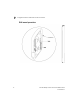
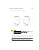
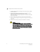
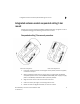
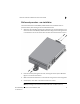
Table Of Contents
- Introduction
- Hardware Installation
- Installation instructions
- Precautions
- Access Point placement
- Integrated antenna model wall mount instructions
- Integrated antenna model suspended ceiling t-bar mount
- External antenna model wall mount instructions
- External antenna model suspended ceiling t-bar mount
- External antenna suspended ceiling tile (Plenum) mount
- Mobility 1220 Access Point external antenna model antenna options
- LED indicators
- Initial Access Point Configuration
- Specifications
- Regulatory Information
- Country Approvals
- Health and Safety Recommendations
- Health and Safety Recommendations
- RF Exposure Guidelines
- Wireless Devices - Countries
- Radio Frequency Interference Requirements—FCC
- Radio Frequency Interference Requirements – Canada
- CE Marking and European Economic Area (EEA)
- Statement of Compliance
- Waste Electrical and Electronic Equipment (WEEE)
- TURKISH WEEE Statement of Compliance
- Mobility 1220 China ROHS Compliance

Integrated antenna model wall mount instructions
2
Brocade Mobility 1220 Access Point Installation Guide 9
53-1002916-01
To maximize the access point’s radio coverage area, Brocade recommends
conducting a site survey to define and document radio interference obstacles
before installing the access point.
Integrated antenna model wall mount instructions
Wall mounting requires hanging the Mobility 1220 Access Point along its width or
length using the two slots on the bottom of the unit. The Mobility 1220 Access Point
can be mounted on to any plaster, wood, or cement wall surface using customer
supplied screw hardware (M3.5 x 0.6 x 20 mm- or equivalent).
Wall mount hardware
•
Two wide-shoulder Phillips pan head self-tapping screws (customer supplied)
•
Two wall anchors (customer supplied)
•
Security cable (optional)
NOTE
The following screws are recommended: (ANSI Standard) #6-18 X 0.875in. Type A or
AB Self-Tapping Screw, or (ANSI Standard Metric) M3.5 X 0.6 X 20mm Type D
Self-Tapping Screw.