
Installation Guide Owner's manual
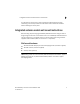
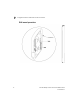
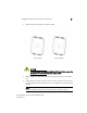
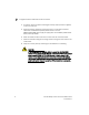
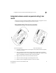
Table Of Contents
- Introduction
- Hardware Installation
- Installation instructions
- Precautions
- Access Point placement
- Integrated antenna model wall mount instructions
- Integrated antenna model suspended ceiling t-bar mount
- External antenna model wall mount instructions
- External antenna model suspended ceiling t-bar mount
- External antenna suspended ceiling tile (Plenum) mount
- Mobility 1220 Access Point external antenna model antenna options
- LED indicators
- Initial Access Point Configuration
- Specifications
- Regulatory Information
- Country Approvals
- Health and Safety Recommendations
- Health and Safety Recommendations
- RF Exposure Guidelines
- Wireless Devices - Countries
- Radio Frequency Interference Requirements—FCC
- Radio Frequency Interference Requirements – Canada
- CE Marking and European Economic Area (EEA)
- Statement of Compliance
- Waste Electrical and Electronic Equipment (WEEE)
- TURKISH WEEE Statement of Compliance
- Mobility 1220 China ROHS Compliance
Integrated antenna model wall mount instructions
2
Brocade Mobility 1220 Access Point Installation Guide 11
53-1002916-01
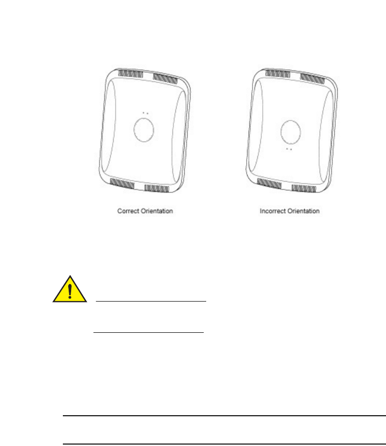
1. Orient the case on the wall by its width or length.
CAUTION
To ensure proper operation of a Mobility 1220 Access Point, ensure it is
mounted in the correct orientation as shown above.
2. Mark two points (for drill holes) 4.08 inches (103.7 mm) apart on a horizontal
line.
3. At each point, drill a hole in the wall, insert an anchor, screw into the anchor the
wall mounting screw and stop when there is 1mm between the screw head and
the wall.
NOTE
When pre-drilling a hole the recommended hole size is 2.8mm (0.11in.).