
Installation Guide Owner's manual
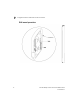
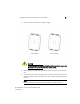
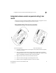
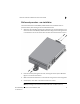
Table Of Contents
- Introduction
- Hardware Installation
- Installation instructions
- Precautions
- Access Point placement
- Integrated antenna model wall mount instructions
- Integrated antenna model suspended ceiling t-bar mount
- External antenna model wall mount instructions
- External antenna model suspended ceiling t-bar mount
- External antenna suspended ceiling tile (Plenum) mount
- Mobility 1220 Access Point external antenna model antenna options
- LED indicators
- Initial Access Point Configuration
- Specifications
- Regulatory Information
- Country Approvals
- Health and Safety Recommendations
- Health and Safety Recommendations
- RF Exposure Guidelines
- Wireless Devices - Countries
- Radio Frequency Interference Requirements—FCC
- Radio Frequency Interference Requirements – Canada
- CE Marking and European Economic Area (EEA)
- Statement of Compliance
- Waste Electrical and Electronic Equipment (WEEE)
- TURKISH WEEE Statement of Compliance
- Mobility 1220 China ROHS Compliance
Integrated antenna model suspended ceiling t-bar mount
2
Brocade Mobility 1220 Access Point Installation Guide 13
53-1002916-01
Integrated antenna model suspended ceiling t-bar
mount
Ceiling mount requires holding the Mobility 1220 Access Point up against a T-bar of
a suspended ceiling grid and twisting the case onto the T-bar.
Suspended ceiling T-bar mount procedure
1. If required, install and attach a Kensington security cable (customer supplied)
to the unit’s lock port.
2. Attach an Ethernet cable from the access point to a device with an 802.3af
compatible power source or use the PWRS-14000-148R power supply to supply
power to the Mobility 1220 Access Point (once fully cabled).
3. Align the bottom of the T-bar with the back of the case.
4. Orient the case by its length, and the length of the T-bar.
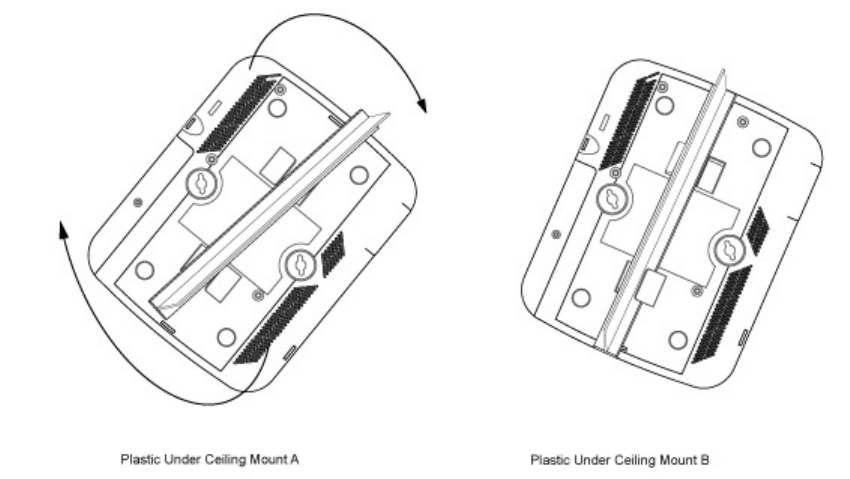
5. Rotate the case 45 degrees clockwise, or about 10 o’clock.