
Installation Guide Owner's manual
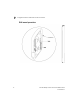
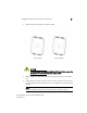
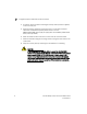
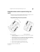
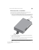
Table Of Contents
- Introduction
- Hardware Installation
- Installation instructions
- Precautions
- Access Point placement
- Integrated antenna model wall mount instructions
- Integrated antenna model suspended ceiling t-bar mount
- External antenna model wall mount instructions
- External antenna model suspended ceiling t-bar mount
- External antenna suspended ceiling tile (Plenum) mount
- Mobility 1220 Access Point external antenna model antenna options
- LED indicators
- Initial Access Point Configuration
- Specifications
- Regulatory Information
- Country Approvals
- Health and Safety Recommendations
- Health and Safety Recommendations
- RF Exposure Guidelines
- Wireless Devices - Countries
- Radio Frequency Interference Requirements—FCC
- Radio Frequency Interference Requirements – Canada
- CE Marking and European Economic Area (EEA)
- Statement of Compliance
- Waste Electrical and Electronic Equipment (WEEE)
- TURKISH WEEE Statement of Compliance
- Mobility 1220 China ROHS Compliance
External antenna model wall mount instructions
2
Brocade Mobility 1220 Access Point Installation Guide 15
53-1002916-01
Wall mount procedure - new installation
This section describes a new Mobility 1220 Access Point installation with no
previous access point existing on the intended wall surface.
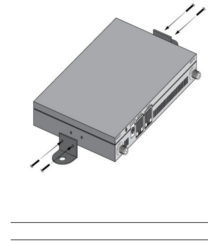
1. Attach the two provided mounting ears (using four ear mounting screws) to the
two narrow ens of the Mobility 1220 Access Point. Align the ears using the built
in ear alignment pin on the access point housing. Torque the screws to 6 lb-in.
2. Place the access point against the wall, ensuring the access point’s Brocade
logo is in the correct orientation.
3. Mark the screw hole locations on a vertical axis using the ear’s mounting holes.
4. At each point, drill a hole in the wall and insert the anchor.
NOTE
When pre-drilling a hole the recommended hole size is 2.8mm (0.11in.).