
Installation Guide Owner's manual
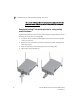
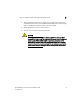
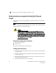
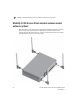
Table Of Contents
- Introduction
- Hardware Installation
- Installation instructions
- Precautions
- Access Point placement
- Integrated antenna model wall mount instructions
- Integrated antenna model suspended ceiling t-bar mount
- External antenna model wall mount instructions
- External antenna model suspended ceiling t-bar mount
- External antenna suspended ceiling tile (Plenum) mount
- Mobility 1220 Access Point external antenna model antenna options
- LED indicators
- Initial Access Point Configuration
- Specifications
- Regulatory Information
- Country Approvals
- Health and Safety Recommendations
- Health and Safety Recommendations
- RF Exposure Guidelines
- Wireless Devices - Countries
- Radio Frequency Interference Requirements—FCC
- Radio Frequency Interference Requirements – Canada
- CE Marking and European Economic Area (EEA)
- Statement of Compliance
- Waste Electrical and Electronic Equipment (WEEE)
- TURKISH WEEE Statement of Compliance
- Mobility 1220 China ROHS Compliance
External antenna model suspended ceiling t-bar mount
2
18 Brocade Mobility 1220 Access Point Installation Guide
53-1002916-01
the unit and void the product warranty. Do not actually connect to the
power source until the cabling portion of the installation is complete.
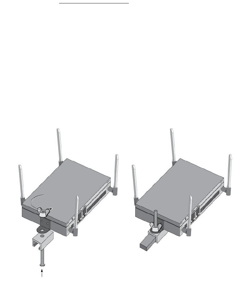
Suspended ceiling T-bar mount procedure - using ceiling
mount hardware
The following installation uses the access point ceiling mounting kit (Part No. SCT-2)
to deploy the access point on a ceiling T-Bar.
1. If required, install and attach a Kensington security cable (customer provided)
to the unit’s lock port.
2. Remove nut from the SCT-2 kit and place assembly and screw through access
point mounting ear.
3. Place the clips from the SCT-2 ceiling mount kit over ceiling T-Bar.
4. Tighten clips using provided nuts.