
Installation Guide Owner's manual
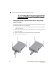
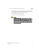
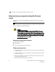
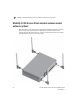
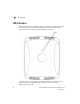
Table Of Contents
- Introduction
- Hardware Installation
- Installation instructions
- Precautions
- Access Point placement
- Integrated antenna model wall mount instructions
- Integrated antenna model suspended ceiling t-bar mount
- External antenna model wall mount instructions
- External antenna model suspended ceiling t-bar mount
- External antenna suspended ceiling tile (Plenum) mount
- Mobility 1220 Access Point external antenna model antenna options
- LED indicators
- Initial Access Point Configuration
- Specifications
- Regulatory Information
- Country Approvals
- Health and Safety Recommendations
- Health and Safety Recommendations
- RF Exposure Guidelines
- Wireless Devices - Countries
- Radio Frequency Interference Requirements—FCC
- Radio Frequency Interference Requirements – Canada
- CE Marking and European Economic Area (EEA)
- Statement of Compliance
- Waste Electrical and Electronic Equipment (WEEE)
- TURKISH WEEE Statement of Compliance
- Mobility 1220 China ROHS Compliance

External antenna suspended ceiling tile (Plenum) mount
2
Brocade Mobility 1220 Access Point Installation Guide 21
53-1002916-01
5. Bring the tile into the ceiling space
6. Attach an Ethernet cable from the access point to a device with an 802.3af
compatible power source or use the PWRS-14000-148R power supply to supply
power to the Mobility 1220 Access Point (once fully cabled).
7. Verify the access point is receiving power by observing the LEDs.
8. Place the ceiling tile back in its frame.
CAUTION
If not using an 802.3af capable device to power the Mobility 1220
Access Point, ensure only the Mobility 1220 Access Point’s designated
power supply (PWRS-14000-148R) is used to supply power to the
access point. Using an incorrectly rated power supply could damage
the unit and void the product warranty. Do not actually connect to the
power source until the cabling portion of the installation is complete.