
Installation Guide Owner's manual
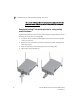
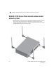
Table Of Contents
- Introduction
- Hardware Installation
- Installation instructions
- Precautions
- Access Point placement
- Integrated antenna model wall mount instructions
- Integrated antenna model suspended ceiling t-bar mount
- External antenna model wall mount instructions
- External antenna model suspended ceiling t-bar mount
- External antenna suspended ceiling tile (Plenum) mount
- Mobility 1220 Access Point external antenna model antenna options
- LED indicators
- Initial Access Point Configuration
- Specifications
- Regulatory Information
- Country Approvals
- Health and Safety Recommendations
- Health and Safety Recommendations
- RF Exposure Guidelines
- Wireless Devices - Countries
- Radio Frequency Interference Requirements—FCC
- Radio Frequency Interference Requirements – Canada
- CE Marking and European Economic Area (EEA)
- Statement of Compliance
- Waste Electrical and Electronic Equipment (WEEE)
- TURKISH WEEE Statement of Compliance
- Mobility 1220 China ROHS Compliance
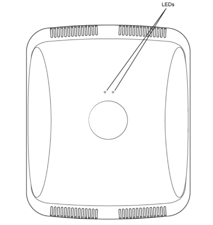
LED indicators
2
24 Brocade Mobility 1220 Access Point Installation Guide
53-1002916-01
LED indicators
Both Integrated Antenna and External Antenna models have LED activity indicators
on the front of the case. With the External Antenna models mounted above a
ceiling, LEDs are at the center of an oval badge on the ceiling.
The LEDs provide a status display indicating error conditions, transmission, and
network activity for the 5 GHz 802.11a/n (amber) radio or the 2.4 GHz
802.11b/g/n (green) radio.