
Product Reference Guide (Supporting software release 4.4.0.0)

Brocade Mobility 5181 Access Point Product Reference Guide 33
53-1002516-01
Mobility 5181 Access Point LED indicators
2
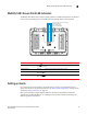
Mobility 5181 Access Point LED indicators
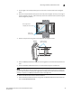
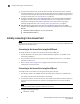
The Mobility 5181 Access Point utilizes four LED indicators. Five LEDs display within four LED slots
on the back of the access point. The five LEDs have the following display and functionality:
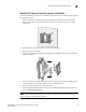
Setting up clients
For a discussion of how to initially test the access point to ensure it can interoperate with the
Clients intended for its operational environment, see “Basic device configuration” on page 37 and
specifically “Testing connectivity” on page 44.
Refer to the LA-5030 & LA-5033 Wireless Networker PC Card and PCI Adapter Users Guide,
available from the Brocade Web site, for installing drivers and client software if operating in an
802.11a/g network environment.
Power Status Solid white indicates the access point is adequately powered.
Error Conditions Solid red indicates the access point is experiencing a problem condition requiring
immediate attention.
Ethernet Activity Flashing white indicates data transfers and Ethernet activity.
802.11a Radio Activity Flickering amber indicates beacons and data transfers over the access point
802.11a radio.
802.11b/g Radio Activity Flickering green indicates beacons and data transfers over the access point
802.11b/g radio.
sym_025
Power and error conditions (split LED)
Data over Ethernet
802.11a radio activity
802.11b/g radio activity