53-1003100-01 20 January 2014 Brocade Mobility Access Point System Reference Guide Supporting software release 5.5.0.
Copyright © 2014 Brocade Communications Systems, Inc. All Rights Reserved. ADX, AnyIO, Brocade, Brocade Assurance, the B-wing symbol, DCX, Fabric OS, ICX, MLX, MyBrocade, OpenScript, VCS, VDX, and Vyatta are registered trademarks, and HyperEdge, The Effortless Network, and The On-Demand Data Center are trademarks of Brocade Communications Systems, Inc., in the United States and/or in other countries. Other brands, products, or service names mentioned may be trademarks of their respective owners.
Contents About This Document Supported hardware and software . . . . . . . . . . . . . . . . . . . . . . . . . . . ix Document conventions . . . . . . . . . . . . . . . . . . . . . . . . . . . . . . . . . . . . . ix Text formatting . . . . . . . . . . . . . . . . . . . . . . . . . . . . . . . . . . . . . . . . ix Notes, cautions, and warnings . . . . . . . . . . . . . . . . . . . . . . . . . . . x Related publications . . . . . . . . . . . . . . . . . . . . . . . . . . . . . . . . . . . . . . .
RF Domain Configuration . . . . . . . . . . . . . . . . . . . . . . . . . . . . . . . . . . 55 RF Domain Sensor Configuration . . . . . . . . . . . . . . . . . . . . . . . . 57 RF Domain Alias Configuration . . . . . . . . . . . . . . . . . . . . . . . . . . 59 System Profile Configuration . . . . . . . . . . . . . . . . . . . . . . . . . . . . . . . 67 General Profile Configuration . . . . . . . . . . . . . . . . . . . . . . . . . . . 68 Profile Radio Power . . . . . . . . . . . . . . . . . . . . . . . . .
MeshConnex Policy . . . . . . . . . . . . . . . . . . . . . . . . . . . . . . . . . . . . . .475 Mesh QoS Policy . . . . . . . . . . . . . . . . . . . . . . . . . . . . . . . . . . . . . . . .481 Passpoint Policy . . . . . . . . . . . . . . . . . . . . . . . . . . . . . . . . . . . . . . . .488 Chapter 7 Network configuration Policy Based Routing (PBR) . . . . . . . . . . . . . . . . . . . . . . . . . . . . . . .491 L2TP V3 Configuration . . . . . . . . . . . . . . . . . . . . . . . . . . . . . . . . . .
Setting the Authentication Configuration . . . . . . . . . . . . . . . . . . . .621 Setting the SNMP Configuration . . . . . . . . . . . . . . . . . . . . . . . . . . .623 SNMP Trap Configuration . . . . . . . . . . . . . . . . . . . . . . . . . . . . . . . . .625 Management Access Deployment Considerations . . . . . . . . . . . . .626 Chapter 11 Diagnostics Fault Management . . . . . . . . . . . . . . . . . . . . . . . . . . . . . . . . . . . . . .629 Crash Files . . . . . . . . . . . . . . . . . . . . .
RF Domain Statistics. . . . . . . . . . . . . . . . . . . . . . . . . . . . . . . . . . . . .707 Health . . . . . . . . . . . . . . . . . . . . . . . . . . . . . . . . . . . . . . . . . . . . .708 Inventory . . . . . . . . . . . . . . . . . . . . . . . . . . . . . . . . . . . . . . . . . . . 711 Devices . . . . . . . . . . . . . . . . . . . . . . . . . . . . . . . . . . . . . . . . . . . . 713 AP Detection . . . . . . . . . . . . . . . . . . . . . . . . . . . . . . . . . . . . . . . . 714 Wireless Clients .
Wireless Client Statistics . . . . . . . . . . . . . . . . . . . . . . . . . . . . . . . . .834 Health . . . . . . . . . . . . . . . . . . . . . . . . . . . . . . . . . . . . . . . . . . . . .834 Details. . . . . . . . . . . . . . . . . . . . . . . . . . . . . . . . . . . . . . . . . . . . .837 Traffic . . . . . . . . . . . . . . . . . . . . . . . . . . . . . . . . . . . . . . . . . . . . .840 WMM TSPEC. . . . . . . . . . . . . . . . . . . . . . . . . . . . . . . . . . . . . . . .841 Association History. .
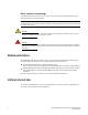
About This Document Supported hardware and software This manual supports the following Access Point, controller and service platform models: • Wireless Controllers – Brocade Mobility RFS4000, Brocade Mobility RFS6000, Brocade Mobility RFS7000 • Service Platforms - Brocade Mobility RFS9510 • Access Points – Brocade Mobility 650 Access Point, Brocade Mobility 6511 Access Point, Brocade Mobility 1220 Access Point, Brocade Mobility 7131 Access Point, Brocade Mobility 1240 Access Point Document conventions T
Notes, cautions, and warnings The following notices and statements are used in this manual. They are listed below in order of increasing severity of potential hazards. NOTE A note provides a tip, guidance or advice, emphasizes important information, or provides a reference to related information. CAUTION A Caution statement alerts you to situations that can be potentially hazardous to you or cause damage to hardware, firmware, software, or data.
Chapter 1 Overview Brocade’ family of Mobility 5.5 supported access points enable high performance with secure and resilient wireless voice and data services to remote locations with the scalability required to meet the needs of large distributed enterprises. Brocade Mobility 6511 Access Point, Brocade Mobility 1220 Access Point, Brocade Mobility 7131 Access Point, and Brocade Mobility 1240 Access Points can now use Mobility software as its onboard operating system.
1 About the Brocade Mobility Software The Mobility architecture is a solution designed for 802.11n networking. It leverages the best aspects of independent and dependent architectures to create a smart network that meets the connectivity, quality and security needs of each user and their applications, based on the availability of network resources including wired networks.
1 Network traffic optimization protects the network from broadcast storms and minimizes congestion on the wired network. The access point managed network provides VLAN load balancing, WAN traffic shaping and optimizations in dynamic host configuration protocol (DHCP) responses and Internet group management protocol (IGMP) snooping for multicast traffic flows in wired and wireless networks.
1 4 Brocade Mobility Access Point System Reference Guide 53-1003100-01
Chapter Web User Interface Features 2 The access point’s resident user interface contains a set of features specifically designed to enable either Virtual Controller AP, Standalone AP or Adopt to Controller functionality. In Virtual Controller AP mode, an access point can manage up to 24 other access points of the same model and share data amongst managed access points. In Standalone mode, an access point functions as an autonomous, non adopted, access point servicing wireless clients.
2 NOTE The access point’s IP address is optimally provided using DHCP. A zero config IP address can also be derived if DHCP resources are unavailable. Using zero config, the last two octets in the IP address are the decimal equivalent of the last two bytes in the access point’s hardcoded MAC address. For example: MAC address - 00:C0:23:00:F0:0A Zero-config IP address - 169.254.240.10 To derive the access point’s IP address using its MAC address: 1.
2 • • • • • • • • • Dialog Box Icons Table Icons Status Icons Configurable Objects Configuration Objects Configuration Operation Icons Access Type Icons Administrative Role Icons Device Icons Global Icons Icon Glossary This section lists global icons available throughout the interface. Logout – Select this icon to log out of the system. This icon is always available and is located at the top right-hand corner of the UI. Add – Select this icon to add a row in a table.
2 These icons indicate the current state of various controls in a dialog. These icons enables you to gather, at a glance, the status of all the controls in a dialog. The absence of any of these icons next to a control indicates the value in that control has not been modified from its last saved configuration. Entry Updated – Indicates a value has been modified from its last saved configuration. Entry Update – States that an override has been applied to a device’s profile configuration.
2 These icons define device status, operations on the wireless controller, or any other action that requires a status being returned to the user. Fatal Error – States there is an error causing a managed device to stop functioning. Error – Indicates an error exits requiring intervention. An action has failed, but the error is not system wide. Warning – States a particular action has completed, but some errors were detected that did not stop the process from completing.
2 AAA Policy – Indicates an Authentication, Authorization and Accounting (AAA) policy has been impacted. AAA policies define RADIUS authentication and accounting parameters. Association ACL – Indicates an Association Access Control List (ACL) configuration has been impacted. An ACL is a set of configuration parameters used to set access to managed resources. The association ACL configures the parameters for controlling device associations. Smart RF Policy – States a Smart RF policy has been impacted.
2 Device Categorization – Indicates a device categorization policy is being applied. This is used by the intrusion prevention system to categorize APs or wireless clients as either neighbors or sanctioned devices. This enables these devices to bypass the intrusion prevention system. Captive Portal – States a captive portal is being applied. Captive portal is used to provide temporary controller, service platform, or access point access to requesting wireless clients.
2 Configuration Objects Icon Glossary Configuration icons are used to define the following: Configuration – Indicates an item capable of being configured by the access point’s interface. View Events / Event History – Defines a list of events. Select this icon to view events or view the event history. Core Snapshots – Indicates a core snapshot has been generated. A core snapshot is a file that records the status of all the processes and memory when a process fails.
2 Access Type Icons Icon Glossary The following icons display a user access type: Web UI – Defines a Web UI access permission. A user with this permission is permitted to access an associated device’s Web UI. Telnet – Defines a TELNET access permission. A user with this permission is permitted to access an access point using TELNET. SSH – Indicates a SSH access permission. A user with this permission is permitted to access an access point using SSH. Console – Indicates a console access permission.
2 Monitor – Indicates a monitor role. This role provides no configuration privileges. A user with this role can view all system configuration but cannot modify them. Help Desk – Indicates help desk privileges. A help desk user is allowed to use troubleshooting tools like sniffers, execute service commands, view or retrieve logs and reboot an access point. Web User – Indicates a Web user privilege. A Web user is allowed accessing the access point’s Web user interface.
Chapter 3 Quick Start Access Points can utilize an initial setup wizard to streamline the process of initially accessing the wireless network. The wizard defines the access point’s operational mode, deployment location, basic security, network and WLAN settings. For instructions on how to use the initial setup wizard, see Using the Initial Setup Wizard on page 3-15.
3 FIGURE 2 Initial Setup Wizard NOTE The Initial Setup Wizard displays the same pages and content for each access point model supported. The only difference being the number of radios configurable by model, as an Brocade Mobility 7131 Access Point model can support up to three radios, Brocade Mobility 1220 Access Point, Brocade Mobility 1240 Access Point models support two radios and Brocade Mobility 6511 Access Point model support a single radio. 4.
3 7. The first page of the Initial Setup Wizard displays the Navigation Panel and Function Highlights for the configuration activities comprising the access point's initial setup. This page also displays options to select the typical or advanced mode for the wizard. FIGURE 3 Initial Setup Wizard - Navigation Panel - Typical Setup Wizard 8. A green check mark to the left of an item in the Navigation Panel defines the listed task as having its minimum required configuration parameters set correctly.
3 NOTE Note the difference in the number of steps between the Typical Setup and Advanced Setup Wizards. 9. Select Save/Commit within each page to save the updates made to that page's configuration. Select Next to proceed to the next page listed in the Navigation Panel. Select Back to revert to the previous screen without saving your updates.
3 FIGURE 5 Initial Setup Wizard - Access Point Settings screen for Typical Setup Wizard 3. Select an Access Point Type from the following options: • Virtual Controller AP - When more than one access points are deployed, a single access point can function as a Virtual Controller AP. Up to 24 access points can be connected to, and managed by a single Virtual Controller AP. These connected access points must be the same model as the Virtual Controller AP.
3 • Adopted to Controller - Select this option when deploying the access point as a controller managed (Dependent mode) access point. Selecting this option closes the Initial AP Setup Wizard. An adopted access point obtains its configuration from a profile stored on its managing controller. Any manual configuration changes are overwritten by the controller upon reboot. For more information on configuring the access point in the Adopted to Controller mode, see Adopt to a controller on page 3-42.
3 Network Topology Selection Typical Setup Wizard Use the Network Topology screen to define how the access point manages network traffic. The available modes are: FIGURE 6 Initial Setup Wizard - Network Topology screen for Typical Setup Wizard • Router Mode - In Router Mode, the access point routes traffic between the local network (LAN) and the Internet or external network (WAN). Router mode is recommended in a deployment supported by just a single access point.
3 NOTE When Bridge Mode is selected, WAN configuration cannot be performed and the Initial Setup Wizard does not display the WAN configuration screen. 3. Select Next. The Typical Setup Wizard displays the LAN Configuration screen to set the access point's LAN interface configuration. For more information, see LAN Configuration on page 3-22. LAN Configuration Typical Setup Wizard Use the LAN Configuration screen to set the access point's DHCP and LAN network address configuration.
3 • Use DHCP - Select the option to enable an automatic network address configuration using DHCP server. • Static IP Address/Subnet - Enter an IP Address and a subnet for the access point's LAN interface. If Use DHCP is selected, this field is not available. When selecting this option, define the following DHCP Server and Domain Name Server (DNS) resources, as those fields will become enabled on the bottom portion of the screen.
3 FIGURE 8 Initial Setup Wizard - WAN Configuration screen of the Typical Setup Wizard Set the following WAN parameters: • Use DHCP - Select the radio control to enable an automatic network address configuration using external DHCP servers. An automatic IP address is configured to the access point’s WAN port using DHCP servers located on the WAN side of the network. • Static IP Address/Subnet - Enter an IP Address and a subnet for the access point's WAN interface.
3 Wireless LAN Setup Typical Setup Wizard A Wireless Local Area Network (WLAN) is a data-communications system and local area network that flexibly extends the functionality of a wired LAN. A WLAN links two or more computers or devices using spread-spectrum or OFDM modulation based technology. WLANs do not require lining up devices for line-of-sight transmission, and are thus, desirable for wireless networking. Roaming users can be handed off from one access point to another, like a cellular phone system.
3 • WLAN Type – Configure the encryption and authentication to use with this WLAN. • No Authentication and No Encryption – Configures a network without any authentication. This means any device can access the network. This option also configures the network without encryption. This means any data transmitted through the network is in plain text. • Captive Portal Authentication and No Encryption – Configures a network that uses a RADIUS server to authenticate users before allowing them on to the network.
3 FIGURE 10 Initial Setup Wizard - RADIUS Server Configuration screen for Typical Setup Wizard 2. Use the Add User button to add a new RADIUS user. A dialog displays where details about the user is entered.
3 FIGURE 11 Initial Setup Wizard - RADIUS Server Configuration - Add User screen for Typical Setup Wizard 3. Use the Add User dialog to provide user information to add to the RADIUS server user database.
3 FIGURE 12 Initial Setup Wizard - Summary And Commit Screen of the Typical Setup Wizard If the configuration displays as intended, select the Save/Commit button to implement these settings to the access point’s configuration. If additional changes are warranted based on the summary, either select the target page from the Navigation Panel, or use the Back button.
3 • • • • Radio Configuration Wireless LAN Setup System Information Summary And Commit Screen To configure the access point using the Advanced Setup Wizard: 1. Select Advanced Setup from the Choose One type to Setup the Access Point field. 2. Select Next. The Advanced Setup Wizard displays the Access Point Settings screen to define the access point's Standalone versus Virtual Controller AP versus functionality. This screen also enables selection of the country of operation.
3 • Virtual Controller AP - When more than one access point is deployed, a single access point can function as a Virtual Controller AP. Up to 24 access points can be connected to, and managed by, a single Virtual Controller AP. These connected access points must be the same model as the Virtual Controller AP. For more information, see Virtual Controller AP Mode on page 3-20. • Standalone AP - Select this option to deploy this access point as an autonomous fat access point.
3 FIGURE 14 Initial Setup Wizard - Access Point Mode screen for Advanced Setup Wizard • Router Mode - In Router Mode, the access point routes traffic between the local network (LAN) and the Internet or external network (WAN). Router mode is recommended in a deployment supported by just a single access point. • Bridge Mode - In Bridge Mode, the access point depends on an external router for routing LAN and WAN traffic.
3 LAN Configuration Advanced Setup Wizard Use the LAN Configuration screen to configure the parameters required for setting a Local Area Network (LAN) on the access point. FIGURE 15 Initial Setup Wizard - LAN Configuration screen for Advanced Setup Wizard 1. Set the following DHCP and Static IP Address/Subnet information for the LAN interface: • Use DHCP - Select the option to enable an automatic network address configuration using DHCP server.
3 • Range - Enter a starting and ending IP Address range for client assignments on the access point's LAN interface. Avoid assigning IP addresses from x.x.x.1 - x.x.x.10 and x.x.x.255, as they are often reserved for standard network services. This is a required parameter. • Default Gateway - Define a default gateway address for use with the default gateway. This is a required parameter. • DNS Forwarding - Select this option to allow a DNS server to translate domain names into IP addresses.
3 FIGURE 16 Initial Setup Wizard - WAN Configuration screen of the Advanced Setup Wizard Set the following WAN parameters: • Use DHCP - Select the radio control to enable an automatic network address configuration using external DHCP servers. An automatic IP address is configured to the access point’s WAN port using DHCP servers located on the WAN side of the network. • Static IP Address/Subnet - Enter an IP Address and a subnet for the access point's WAN interface.
3 Radio Configuration Advanced Setup Wizard Use the Radio Configuration screen to define radio support for the 2.4 GHz radio band, 5.0 GHz radio band or set the radio as a dedicated sensor. NOTE The Radio Configuration screen displays separate configurable fields for each access point radio. Supported access point models can have from one to three (Brocade Mobility 7131 Access Point) radios.
3 • Radio Frequency Band - Select the 2.4 GHz or 5.0 GHz radio band to use with the radio when selected as a Data Radio. The selected band is used for WLAN client support. Consider selecting one radio for 2.4 GHz and another for 5.0 GHz support (if using a dual or three radio model) when supporting clients in both the 802.11bg and 802.11n bands. • Power Level - Use the spinner control to select a 1 - 23 dBm minimum power level to assign to this radio in selected 2.4 GHz or 5.0 GHz band.
3 FIGURE 18 Initial Setup Wizard - WAN Configuration screen for Advanced Setup Wizard Set the following WLAN1 Configuration parameters: • SSID – Configure the SSID for the WLAN. • WLAN Type – Configure the encryption and authentication to use with this WLAN. • No Authentication and No Encryption – Configures a network without any authentication. This means any device can access the network. This option also configures the network without encryption.
3 • Onboard RADIUS Server – When selected, a new screen displays where further configuration can be performed. For more information, see RADIUS Server Configuration on page 3-26. • PSK authentication, WPA2 encryption – Configures a network that uses PSK authentication and WPA2 encryption. Select this option to implement a pre-shared key that must be correctly shared between the access point and requesting clients on the WLAN • WPA Key – Provide a 64 character HEX key or 8-63 character ASCII key.
3 FIGURE 19 Initial Setup Wizard - System Information screen for the Advanced Setup Wizard • Location - Provide the location of the access point. • Contact - Specify the contact information for the administrator. The credentials provided should accurately reflect the individual responding to service queries. • Country - Select the country where the access point is deployed. The access point prompts for the correct country code on the first login.
3 Summary And Commit Screen Advanced Setup Wizard The Summary And Commit screen displays an overview of the updates made using the Advanced Setup Wizard. There is no user intervention or additional settings required. This screen is an additional means of validating the configuration before it is deployed. However, if a screen displays settings not intended as part of the initial configuration, the screen can be selected from within the Navigation Panel and its settings modified accordingly.
3 Adopt to a controller Advanced Setup Wizard When the access point is powered on for the first time, it looks for a wireless controller on the default subnet running the same firmware version and automatically adopts to it. When Adopted to Controller is selected, further configuration settings are displayed in the same screen. Select Automatic controller discovery to enable the access point to be discovered and adopted using layer 2 settings.
Chapter 4 Dashboard The dashboard allows network administrators to review and troubleshoot the operation of the devices comprising the access point managed network. Use the dashboard to review the current network topology, assess the network’s component health and diagnose problematic device behavior. By default, the Dashboard screen displays the System Dashboard, which is the top level in the device hierarchy.
4 FIGURE 1 Dashboard - Health tab Dashboard Conventions The Dashboard screen displays device information using the following conventions: • Health – Displays the state of the access point managed network. • Inventory – Displays the physical devices managed by the access point. Health Dashboard Conventions The Health tab displays performance and utilization data for the access point managed network.
4 FIGURE 2 Dashboard - Health tab For more information see: • • • • Device Details Radio RF Quality Index Radio Utilization Index Client RF Quality Index Device Details Health The Device Details field displays model and version information.
4 FIGURE 3 Dashboard - Health tab - Device Details field The Device Details field displays the name assigned to the selected access point, factory encoded MAC address, primary IP address, model type, RF Domain, software version, uptime, CPU and RAM information and system clock. Use this data to determine whether a software upgrade is warranted, or if the system clock needs adjustment. Periodically select Refresh (at the bottom of the screen) to update the data displayed.
4 The access point’s RF Domain allows an administrator to assign configuration data to multiple devices deployed in a common coverage area, such as in a floor, building or site. The RF Domain contains policies that can determine a Smart RF or WIPS configuration. Use this diagnostic information to define measures to improve radio performance in respect to wireless client load and radio band. Periodically select Refresh (at the bottom of the screen) to update the RF quality data.
4 FIGURE 6 Dashboard - Health tab - Client RF Quality Index field 1. The Client RF Quality Index displays the following: Worst 5 Lists the worst 5 performing client radios connected to the access point. The RF Quality Index measures the overall effectiveness of the RF environment as a percentage. Its a function of the connect rate in both directions, as well as the retry rate and the error rate.
4 FIGURE 7 Dashboard - Inventory tab The Inventory tab is partitioned into the following fields: • • • • Radio Types WLAN Utilization Wireless Clients Clients by Radio Type Radio Types Inventory The Radio Types field displays the total number and types of radios managed by the selected access point.
4 FIGURE 8 Dashboard - Inventory tab - Radio Types field Refer to the Total Radios column to review the number of managed radios. Additionally, use the bar graphs to assess the number WLANs utilized by supported radio bands. Periodically select Refresh (at the bottom of the screen) to update the radio information. WLAN Utilization Inventory The WLAN Utilization field displays the top 5 WLANs utilized by this access point in respect to client support.
4 FIGURE 10 Dashboard - Inventory tab - Wireless Clients field Information within the Wireless Clients field is presented in two tables. The first table lists the total number of wireless clients managed by this access point. The second table lists an ordered ranking of radios based on their supported client count. Use this information to assess if an access point managed radio is optimally deployed in respect to its radio type and intended client support requirements.
4 Network View Dashboard The Network View displays device topology association between a selected access point, its RF Domain and its connected clients. Access points and clients can be selected and viewed using various color schemes in respect to neighboring access points, connected devices and performance criteria. Display options can be utilized to review device performance and utilization, as well as the RF band, channel and vendor. For more information, see Network View Display Options on page 4-53.
4 Network View Display Options Network View 1. Select the blue Options link right under the Network View banner to display a menu for different device interaction display options. FIGURE 14 Network View - Display Options 2. The following display filter options are available: • None - Select this option to keep the Network View display as it currently appears, without any additional color or device interaction adjustments.
4 Device Specific Information Network View A device specific information screen is available for individual devices selected from within the Network View (not the System Browser). The screen displays the name assigned to the device, its model, factory encoded MAC address, number of radios within the device, number of connected clients, as well as the highest and lowest reported quality, utilization and Signal to Noise Ratio (SNR). This information cannot be modified by the administrator.
Chapter Device Configuration 5 Access points can either be assigned unique configurations to support a particular deployment objective or have an existing RF Domain or profile configuration modified (overridden) to support a requirement that deviates its configuration from the configuration shared by its peer access points.
5 However, an access point’s RF Domain configuration may need periodic refinement from its original RF Domain designation. Unlike a RFS series wireless controller, an access point supports just a single RF domain. Thus, administrators should be aware that overriding an access point’s RF Domain configuration results in a separate configuration that must be managed in addition to the RF Domain configuration. Thus, a configuration should only be overridden when needed.
5 4. Define the following Basic Configuration values for the access point RF Domain: Location Assign the physical location of the RF Domain. This name could be as specific as the floor of a building, or as generic as an entire site. The location defines the physical area where a common set of access point configurations are deployed and managed by the RF Domain policy. Contact Provide the name of the contact E-mail (or administrator) assigned to respond to events created by or impacting the RF Domain.
5 The Brocade’ Wireless Intrusion Protection System (WIPS) protects wireless client and access point radio traffic from attacks and unauthorized access. WIPS provides tools for standards compliance and around-the-clock wireless network security in a distributed environment. WIPS allows administrators to identify and accurately locate attacks, rogue devices and network vulnerabilities in real time and permits both a wired and wireless lockdown of wireless device connections upon acknowledgement of a threat.
5 6. Provide the numerical (non DNS) IP Address of each server used as a WIPS sensor server by the RF Domain. 7. Use the spinner control to specify the Port of each WIPS server. The default port is 443. 8. Select OK to save the changes to the AirDefense WIPS configuration, or select Reset to revert to the last saved configuration.
5 • Network Service Alias Network Basic Alias RF Domain Configuration A basic alias is a set of configurations that consist of VLAN, Host, Network and Address Range alias configurations. VLAN configuration is a configuration for optimal VLAN re-use and management for local and remote deployments. A host alias configuration is for a particular host device’s IP address. A network alias configuration is utilized for an IP address on a particular network.
5 FIGURE 3 RF Domain - Basic Alias screen 5. Select + Add Row to define VLAN Alias settings: Use the VLAN Alias field to create unique aliases for VLANs that can be used at different deployments. For example, if a named VLAN is defined as 10 for the central network, and the VLAN is set at 26 at a remote location, the VLAN can be overridden at the deployment location with an alias.
5 • • • • IP Firewall Rules L2TPv3 Switchport Wireless LANs 6. Select + Add Row to define Address Range Alias settings: Use the Address Range Alias field to create aliases for IP address ranges that can be utilized at different deployments. For example, if an ACL defines a pool of network addresses as 192.168.10.10 through 192.168.10.100 for an entire network, and a remote location’s network range is 172.16.13.20 through 172.16.13.110, the remote location’s ACL can be overridden using an alias.
5 Use the Network Alias field to create aliases for IP networks that can be utilized at different deployments. For example, if a central network ACL defines a network as 192.168.10.0/24, and a remote location’s network range is 172.16.10.0/24, the ACL can be overridden at the remote location to suit their local (but remote) requirement. At the remote location, the ACL functions with the 172.16.10.0/24 network. A new ACL need not be created specifically for the remote deployment.
5 3. Select RF Domain. 4. Select the Network Group Alias tab. The following screen displays: FIGURE 4 RF Domain - Network Group Alias screen Name Displays the administrator assigned name of the network group alias. Host Displays all host aliases configured in this network group alias. Displays a blank column if no host alias is defined. Network Displays all network aliases configured in this network group alias. Displays a blank column if no network alias is defined. 5.
5 FIGURE 5 RF Domain - Network Group Alias Add screen 6. If adding a new Network Group Alias, provide it a name of up to 32 characters. NOTE The Network Group Alias Name always starts with a dollar sign ($). 7. Define the following network group alias parameters: Host Specify the Host IP address for up to eight IP addresses supporting network aliasing. Select the down arrow to add the IP address to the table. Network Specify the netmask for up to eight IP addresses supporting network aliasing.
5 Network Service Alias RF Domain Configuration A network service alias is a set of configurations that consist of protocol and port mappings. Both source and destination ports are configurable. For each protocol, up to 2 source port ranges and up to 2 destination port ranges can be configured. A maximum of 4 protocol entries can be configured per network service alias.
5 FIGURE 7 RF Domain - Network Service Alias Add screen 6. If adding a new Network Service Alias, provide it a name up to 32 characters. NOTE The Network Service Alias Name always starts with a dollar sign ($). 7. Within the Range field, use the + Add Row button to specify the Start IP address and End IP address for the service alias range or double-click on an existing service alias range entry to edit it. Protocol Specify the protocol for which the alias has to be created.
5 An access point profile enables an administrator to assign a common set of configuration parameters and policies to access points of the same model. Profiles can be used to assign common or unique network, wireless and security parameters to across a large, multi segment, site. The configuration parameters within a profile are based on the hardware model the profile was created to support.
5 An access point profile requires unique clock synchronization settings as part of its general configuration. Network time protocol (NTP) manages time and/or network clock synchronization within the access point managed network. NTP is a client/server implementation. The access point periodically synchronizes its clock with a master clock (an NTP server). For example, the access point resets its clock to 07:04:59 upon reading a time of 07:04:59 from its designated NTP server.
5 4. Select + Add Row below the Network Time Protocol (NTP) table to define the configurations of NTP server resources used to obtain system time. Up to 3 NTP servers can be configured. Set the following parameters to define the NTP configuration: AutoKey Select this option to enable an autokey configuration for the NTP resource. The default setting is disabled. Key If an autokey is not being used, manually enter a 64 character maximum key the access point and NTP resource share to securely interoperate.
5 3. Select System Profile from the options on left-hand side of the UI. 4. Select Power. A screen displays where the access point profile’s power mode can be defined. FIGURE 9 5. Profile - Power screen Use the Power Mode drop-down menu to set the Power Mode Configuration on this AP. NOTE Single radio model access points always operate using a full power configuration. The power management configurations described in this section do not apply to single radio access point models.
5 8. Select Range when range is preferred over performance for broadcast/multicast (group) traffic. The data rates used for range are the lowest defined basic rates. Throughput is the default setting for both 802.3af and 802.3at. 9. Select OK to save the changes made to the access point power configuration.
5 FIGURE 10 Profile Adoption screen 5. Define the Preferred Group used as optimal group of Virtual Controller for adoption. The name of the preferred group cannot exceed 64 characters. 6. Select the VLAN option to define a VLAN the access point’s associating Virtual Controller AP is reachable on. VLANs 0 and 4,095 are reserved and cannot be used. This setting is disabled by default. Define the Hello Interval value in seconds.
5 7. Enter Controller Hostnames as needed to define resources for adoption. Click +Add Row to add controllers. Set the following parameters to define Controller Hostnames: Host Use the drop-down menu to specify whether the controller adoption resource is defined as a (non DNS) IP address or a hostname. Once defined, provide the numerical IP or hostname. A hostname cannot exceed 64 characters. Pool Use the spinner controller to set a pool of either 1 or 2.
5 FIGURE 11 Profile Wired 802.1X screen 5. Set the following Wired 802.1x Settings: Dot1x Authentication Control Select this option to globally enable 802.1x authentication for the selected device. This setting is disabled by default. Dot1x AAA Policy Use the drop-down menu to select an AAA policy to associate with wired 802.1x traffic. If a suitable AAA policy does not exist, click the Create icon to create a new policy or the Edit icon to modify an existing policy.
5 1. Select the Configuration tab from the Web UI. 2. Select Devices. 3. Select System Profile from the options on left-hand side of the UI. 4. Expand the Interface menu and select Ethernet Ports. FIGURE 12 Profile Interfaces - Ethernet Ports screen 5. Refer to the following to assess port status, mode and VLAN configuration: Name Displays the physical port name reporting runtime data and statistics. Supported ports vary depending on model. Type Displays the physical port type.
5 Mode Displays the profile’s current switching mode as either Access or Trunk. If Access is listed, the port accepts packets only from the native VLAN. Frames are forwarded out the port untagged with no 802.1Q header. All frames received on the port are expected as untagged and mapped to the native VLAN. If set to Trunk, the port allows packets from a list of VLANs added to the trunk. A port configured as Trunk supports multiple 802.1Q tagged VLANs and one Native VLAN which can be tagged or untagged.
5 7. Set the following Ethernet port Properties: Description Enter a brief description for the port (64 characters maximum). The description should reflect the port’s intended function to differentiate it from others with similar configurations. Admin Status Select the Enabled radio button to define this port as active to the profile it supports. Select the Disabled radio button to disable this physical port in the profile. It can be activated at any future time when needed.
5 9. Define the following Switching Mode parameters to apply to the Ethernet port configuration: Mode Select either the Access or Trunk radio button to set the VLAN switching mode over the port. If Access is selected, the port accepts packets only form the native VLANs. Frames are forwarded out the port untagged with no 802.1Q header. All frames received on the port are expected as untagged and are mapped to the native VLAN.
5 FIGURE 14 Ethernet Ports - Security tab 13. Refer to the Access Control field. As part of the port’s security configuration, Inbound IP and MAC address firewall rules are required. Use the Inbound IP Firewall Rules and Inbound MAC Firewall Rules drop-down menus to select the firewall rules to apply to this profile’s Ethernet port configuration. The firewall inspects IP and MAC traffic flows and detects attacks typically not visible to traditional wired firewall appliances. 14.
5 NOTE Some vendor solutions with VRRP enabled send ARP packets with Ethernet SMAC as a physical MAC and inner ARP SMAC as VRRP MAC. If this configuration is enabled, a packet is allowed, despite a conflict existing. 16. Set the following 802.1X Settings: Host Mode Use the drop-down menu to select the host mode configuration to apply to this port. Options include single-host or multi-host. The default setting is single-host. Guest VLAN Specify a guest VLAN for this port from 1 - 4094.
5 Max Reauthenticate Count Configures the number of times an attempt is made to reauthenticate a controlled port. When exceeded, the controlled port is set as unauthorized. Maximum Request Configures the number of times an attempt is made to authenticate with the EAP server before returning an authentication failed message to the device requesting authorization using the controlled port. Quiet Period Configures the duration in seconds where no attempt is made to reauthenticate a controlled port.
5 FIGURE 15 Ethernet Ports - Spanning Tree tab Refer to the PortFast field to define the following: Enable PortFast PortFast reduces the time taken for a port to complete STP. PortFast must only be enabled on ports on the wireless controller which are directly connected to a server/workstation and not to another hub or controller. PortFast can be left unconfigured on the access point.
5 Refer to the MSTP Configuration field to define the following: Enable as Edge Port Select to enable the port as an Edge Port for MSTP. An Edge Port is a port known to connect to a LAN which has no other bridges attached to it or is directly connected to an user device. Link Type Select either the Point-to-Point or Shared radio button. Selecting Point-to-Point indicates the port should be treated as connected to a point-to-point link.
5 A Virtual Interface is required for layer 3 (IP) access to provide layer 3 service on a VLAN. The Virtual Interface defines which IP address is associated with each VLAN ID the access point is connected to. A Virtual Interface is created for the default VLAN (VLAN 1) to enable remote administration. A Virtual Interface is also used to map VLANs to IP address ranges. This mapping determines the destination networks for routing.
5 6. Select Add to define a new Virtual Interface configuration, Edit to modify the configuration of an existing Virtual Interface or Delete to permanently remove a selected Virtual Interface. FIGURE 17 Virtual Interfaces - Basic Configuration tab The Basic Configuration screen displays by default regardless of a whether a new Virtual Interface is being created or an existing one is being modified. 7. If creating a new Virtual Interface, use the Name spinner control to define a numeric ID from 1 - 4094.
5 9. Set the following network information from within the IP Addresses field: Enable Zero Configuration The access point can use Zero Config for IP assignments on an individual virtual interface basis. Select Primary to use Zero Config as the designated means of providing an IP address, this eliminates the means to assign one manually. Selecting Secondary is preferred when wanting the option to either use Zero Config or manual assignments.
5 FIGURE 18 Virtual Interfaces - Security tab 14. Use the Inbound IP Firewall Rules drop-down menu to select the firewall rule configuration to apply to this Virtual Interface. The firewall inspects and packet traffic to and from connected clients. If a firewall rule does not exist suiting the data protection needs of this Virtual Interface, select the Create icon to define a new firewall rule configuration or the Edit icon to modify an existing configuration.
5 FIGURE 19 Profile Interfaces - Port Channels screen 1. Select the Configuration tab from the Web UI. 2. Select Devices. 3. Select System Profile from the options on left-hand side of the UI. 4. Expand the Interface menu and select Port Channels. 5. Refer to the following to review existing port channel configurations and their current status: Name Displays the port channel’s numerical identifier assigned to it when it was created. The numerical name cannot be modified as part of the edit process.
5 FIGURE 20 7. Port Channels - Basic Configuration tab Set the following port channel Properties: Description Enter a brief description for the port channel (64 characters maximum). The description should reflect the port channel’s intended function. Admin Status Select the Enabled radio button to define this port channel as active to the controller profile it supports. Select the Disabled radio button to disable this port channel configuration within the profile.
5 9. Define the following Switching Mode parameters to apply to the port channel configuration: Mode Select either the Access or Trunk radio button to set the VLAN switching mode over the port channel. If Access is selected, the port channel accepts packets only form the native VLANs. Frames are forwarded out the port untagged with no 802.1Q header. All frames received on the port are expected as untagged and are mapped to the native VLAN.
5 FIGURE 21 Port Channels - Security tab 12. Refer to the Access Control field. As part of the port channel’s security configuration, Inbound IP and MAC address firewall rules are required. Use the Inbound IP Firewall Rules and Inbound MAC Firewall Rules drop-down menus to select firewall rules to apply to this profile’s port channel configuration. The firewall inspects IP and MAC traffic flows and detects attacks typically not visible to traditional wired firewall appliances.
5 13. Select OK to save the changes to the security configuration. Select Reset to revert to the last saved configuration. 14. Select the Spanning Tree tab. FIGURE 22 Port Channels - Spanning Tree tab 15. Define the following PortFast parameters for the port channel’s MSTP configuration: Enable PortFast PortFast reduces the time required for a port to complete a MSTP state change from Blocked to Forward.
5 16. Set the following MSTP Configuration parameters for the port channel: Enable as Edge Port Select this option to define this port as an edge port. Using an edge (private) port, you can isolate devices to prevent connectivity over this port channel. This setting is disabled by default. Link Type Select either the Point-to-Point or Shared radio button. Selecting Point-to-Point indicates the port should be treated as connected to a point-to-point link.
5 Access Point Radio Configuration Profile Interface Configuration An access point profile can have its radio configuration modified once its radios have successfully associated to the network. To define a access point radio configuration: 1. Select the Configuration tab from the Web UI. 2. Select Devices. 3. Select System Profile from the options on left-hand side of the UI. 4. Expand the Interface menu and select Radios. FIGURE 23 Access Point Radios screen 5.
5 Admin Status A red “X” defines the radio’s status as currently disabled. A green check mark designates the status as enabled. RF Mode Displays whether each listed radio is operating in the 802.11a/n or 802.11b/g/n radio band. If the radio is a dedicated sensor, it will be listed as a sensor to define the radio as not providing typical WLAN support. If the radio is a client-bridge, it will be listed as a client bridge and does not provide typical WLAN support.
5 8. Define the following radio configuration parameters from within the Properties field: Description Provide or edit a description (1 - 64 characters) for the radio that helps differentiate it from others with similar configurations. Admin Status Either select the Disabled or Enabled radio button to define this radio’s current status within the network. When defined as Enabled, the access point is operational and available for client support.
5 Antenna Gain Set the antenna from 0.00 - 30.00 dBm. The access point’s Power Management Antenna Configuration File (PMACF) automatically configures the access point’s radio transmit power based on the antenna type, its antenna gain (provided here) and the deployed country’s regulatory domain restrictions. Once provided, the access point calculates the power range.
5 10. Set the following profile WLAN Properties for the selected access point radio: Beacon Interval Set the interval between radio beacons in milliseconds (either 50, 100 or 200). A beacon is a packet broadcast by adopted radios to keep the network synchronized. Included in a beacon is information such as the WLAN service area, the radio address, the broadcast destination addresses, a time stamp, and indicators about traffic and delivery such as a DTIM.
5 FIGURE 25 Access Point Radio - WLAN Mapping tab 12. Refer to the WLAN Mapping/Mesh Mapping field to set WLAN BSSID assignments for an existing access point deployment. Administrators can assign each WLAN its own BSSID. If using a single-radio access point, there are 8 BSSIDs available. If using a dual-radio access point there are 8 BSSIDs for the 802.11b/g/n radio and 8 BSSIDs for the 802.11a/n radio. Each supported access point model can support up to 8 BSS IDs. 13.
5 FIGURE 26 Access Point Radio - Mesh Legacy tab Use the Legacy Mesh screen to define how mesh connections are established and the number of links available amongst access points within the Mesh network. 18. Define the following Mesh Settings: Mesh Options include Client, Portal and Disabled. Select Client to scan for mesh portals, or nodes that have connection to portals, and then connect through them.
5 FIGURE 27 Access Point Radio - Advanced Settings tab 22. Refer to the Aggregate MAC Protocol Data Unit (A-MPDU) field to define how MAC service frames are aggregated by the access point radio. A-MPDU Modes Use the drop-down menu to define the A-MPDU mode supported. Options include Transmit Only, Receive Only, Transmit and Receive and None. The default value is Transmit and Receive. Using the default value, long frames can be both sent and received (up to 64 KB).
5 Set the following Ekahau Properties for the selected access point radio: Forwarding Host Use the Forward Host text area to provide the IP address of the Ekahau Engine. Forwarding Port Use the Forward Port spinner to configure the port on which to forward captured packets to the Ekahau Engine. MAC to be forwarded Use the text area to provide a MAC address that identifies that the packet is received from Ekahau tags.
5 802.11n MCS rates are defined as follows both with and without short guard intervals (SGI): 104 MCS Index Number of Streams 20 MHz No SGI 20 MHz With SGI 40 MHz No SGI 40MHz With SGI 0 1 6.5 7.2 13.5 15 1 1 13 14.4 27 30 2 1 19.5 21.7 40.5 45 3 1 26 28.9 54 60 4 1 39 43.4 81 90 5 1 52 57.8 108 120 6 1 58.5 65 121.5 135 7 1 65 72.2 135 150 MCS Index Number of Streams 20 MHz No SGI 20 MHz With SGI 40 MHz No SGI 40MHz With SGI 0 2 13 14.
5 802.11ac MCS rates are defined as follows both with and without short guard intervals (SGI): MCS Index 20 MHz No SGI 20 MHz With SGI 40 MHz No SGI 40MHz With SGI 80 MHz No SGI 80MHz With SGI 0 6.5 7.2. 13.5 15 29.3 32.5 1 13 14.4 27 30 58.5 65 2 19.5 21.7 40.5 45 87.8 97.5 3 26 28.9 54 60 117 130 4 39 43.3 81 90 175.5 195 5 52 57.8 108 120 234 260 6 58.5 65 121.5 135 263.3 292.5 7 65 72.2 135 150 292.5 325 8 78 86.
5 3. Select System Profile from the options on left-hand side of the UI. 4. Expand the Interface menu and select WAN Backhaul. FIGURE 28 Profile Interface - WAN Backhaul screen 5. Refer to the WAN (3G) Backhaul configuration to specify the access point’s WAN card interface settings: WAN Interface Name Displays the WAN Interface name for the WAN 3G Backhaul card. Enable WAN (3G) Select this option to enable 3G WAN card support on the access point.
5 7. Use the NAT Direction field to specify the NAT direction used with the access point’s WAN card. Options include Inside, Outside or None. The default is None. Configure the Inbound IP Firewall Rules. Use the drop-down menu to select a firewall (set of IP access connection rules) to apply to the PPPoE client connection.
5 To provide this point-to-point connection, each PPPoE session learns the Ethernet address of a remote PPPoE client, and establishes a session. PPPoE uses both a discover and session phase to identify a client and establish a point-to-point connection. By using such a connection, a Wireless WAN failover is available to maintain seamless network access if the access point’s Wired WAN were to fail.
5 FIGURE 29 Profile Interface - PPPoE screen 5. Use the Basic Settings field to enable PPPoE and define a PPPoE client. Enable PPPoE Select Enable to support a high speed client mode point-to-point connection using the PPPoE protocol. The default setting is disabled. Service Enter the 128 character maximum PPPoE client service name provided by the service provider. DSL Modem Network (VLAN) Use the spinner control to set the PPPoE VLAN (client local network) connected to the DSL modem.
5 6. Define the following Authentication parameters for PPPoE client interoperation: Username Provide the 64 character maximum username used for authentication support by the PPPoE client. Password Provide the 64 character maximum password used for authentication by the PPPoE client. Use the Show option to view the actual characters comprising the password.
5 An access point profile network configuration process consists of the following: • • • • • • • • • • • • • • DNS Configuration ARP L2TPv3 Profile Configuration IGMP Snooping Quality of Service (QoS) Spanning Tree Configuration Routing Dynamic Routing (OSPF) Forwarding Database Bridge VLAN Cisco Discovery Protocol Configuration Link Layer Discovery Protocol Configuration Miscellaneous Network Configuration Alias Before beginning any of the profile network configuration activities described in the sectio
5 FIGURE 30 Network - DNS screen 5. Provide a default Domain Name used when resolving DNS names. The name cannot exceed 64 characters. 6. Set the following DNS configuration data: Enable Domain Lookup Select this option to enable DNS. When enabled, human friendly domain names can be converted into numerical IP destination addresses. This feature is enabled by default.
5 special format to all the machines on the LAN to see if one machine knows that it has that IP address associated with it. A machine that recognizes the IP address as its own returns a reply. ARP updates the ARP cache for future reference, and then sends the packet to the MAC address that replied. To define an ARP supported configuration: 1. Select the Configuration tab from the Web UI. 2. Select Devices. 3. Select System Profile from the options on left-hand side of the UI. 4.
5 L2TPv3 Profile Configuration Profile Network Configuration L2TP V3 is an IETF standard used for transporting different types of layer 2 frames in an IP network (and access point profile). L2TP V3 defines control and encapsulation protocols for tunneling layer 2 frames between two IP nodes. Use L2TP V3 to create tunnels for transporting layer 2 frames.
5 FIGURE 32 Network - L2TPv3 screen - General tab 5. Set the following General Settings for an L2TPv3 profile configuration: Host Name Define a 64 character maximum hostname to specify the name of the host that’s sent tunnel messages. Tunnel establishment involves exchanging 3 message types (SCCRQ, SCCRP and SCCN) with the peer. Tunnel IDs and capabilities are exchanged during the tunnel establishment with the host.
5 FIGURE 33 7. Network - L2TPv3 screen - T2TP tunnel tab Review the following L2TPv3 tunnel configuration data: Name Displays the name of each listed L2TPv3 tunnel assigned upon creation. Local IP Address Lists the IP address assigned as the local tunnel end point address, not the interface IP address. This IP is used as the tunnel source IP address. If this parameter is not specified, the source IP address is chosen automatically based on the tunnel peer IP address.
5 8. Either select Add to create a new L2TPv3 tunnel configuration, Edit to modify an existing tunnel configuration or Delete to remove a tunnel from those available to this profile. FIGURE 34 Network - L2TPv3 screen - Add T2TP Tunnel Configuration 9. If creating a new tunnel configuration, assign it a 31 character maximum Name.
5 10. Define the following Settings required for the L2TP tunnel configuration: Local IP Address Enter the IP address assigned as the local tunnel end point address, not the interface IP address. This IP is used as the tunnel source IP address. If this parameter is not specified, the source IP address is chosen automatically based on the tunnel peer IP address. This parameter is applicable when establishing the tunnel and responding to incoming tunnel create requests.
5 FIGURE 35 Network - L2TPv3 screen - Add T2TP Peer Configuration 12. Define the following Peer parameters: Peer ID Define the primary peer ID used to set the primary and secondary peer for tunnel failover. If the peer is not specified, tunnel establishment does not occur. However, if a peer tries to establish a tunnel with this access point, it creates the tunnel if the hostname and/or Router ID matches.
5 15. Define the following Session parameters: Name Enter a 31 character maximum session name. There is no idle timeout for a tunnel. A tunnel is not usable without a session and a subsequent session name. The tunnel is closed when the last session tunnel session is closed. Pseudowire ID Define a psuedowire ID for this session. A pseudowire is an emulation of a layer 2 point-to-point connection over a packet-switching network (PSN).
5 18. Refer to the following manual session configurations to determine whether a session should be created or modified: IP Address Lists the IP address assigned as the local tunnel end point address, not the interface IP address. This IP is used as the tunnel source IP address. If this parameter is not specified, the source IP address is chosen automatically based on the tunnel peer IP address. This parameter is applicable when establishing the session and responding to incoming requests.
5 20. Set the following session parameters: Name Define a 31 character maximum name for this tunnel session. Each session name represents a single data stream. IP Address Specify the IP address used as a tunnel source IP address. If not specified, the tunnel source IP address is selected automatically based on the tunnel peer IP address. This address is applicable only for initiating the tunnel.
5 3. Select System Profile from the options on left-hand side of the UI. Expand the Network menu and select IGMP Snooping. FIGURE 38 IGMP Snooping screen Set the following parameters to configure general IGMP Snooping values. Enable IGMP Snooping Select this option to enable IGMP Snooping on the access point. This feature is enabled by default. Forward Unknown Multicast Packets Select this option to enable the access point to forward multicast packets from unregistered multicast groups.
5 Set the following for IGMP Querier configuration: Enable IGMP Querier Select this option to enable IGMP querier. IGMP snoop querier is used to keep host memberships alive. It is primarily used in a network where there is a multicast streaming server and hosts subscribed to the server and no IGMP querier present. The controller can perform the IGMP querier role. An IGMP querier sends out periodic IGMP query packets. Interested hosts reply with an IGMP report packet.
5 FIGURE 39 Network - Quality of Service (QoS) screen 5. Set the following parameters for IP DSCP mappings for untagged frames: DSCP Lists the DSCP value as a 6-bit parameter in the header of every IP packet used for packet classification. 802.1p Priority Assign a 802.1p priority as a 3-bit IP precedence value in the Type of Service field of the IP header used to set the priority. The valid values for this field are 0-7. Up to 64 entries are permitted.
5 The Multiple Spanning Tree Protocol (MSTP) provides an extension to RSTP to optimize the usefulness of VLANs. MSTP allows for a separate spanning tree for each VLAN group, and blocks all but one of the possible alternate paths within each spanning tree topology. If there’s just one VLAN in the access point managed network, a single spanning tree works fine.
5 FIGURE 40 Network - Spanning Tree screen 5. Set the following MSTP Configuration parameters: MSTP Enable Select this option to enable MSTP for this profile. MSTP is disabled by default, so enable this setting if requiring different (groups) of VLANs with the profile supported network segment. Max Hop Count Define the maximum number of hops the BPDU considers valid in the spanning tree topology. The available range is from 7 -127. The default setting is 20.
5 Cisco MSTP Interoperability Select either the Enable or Disable radio buttons to enable/disable interoperability with Cisco’s version of MSTP, which is incompatible with standard MSTP. This setting is disabled by default. Hello Time Set a BPDU hello interval from 1 - 10 seconds. BPDUs are exchanged regularly (every 2 seconds by default) and enable supported devices to keep track of network changes and start/stop port forwarding as required.
5 To create static routes: 1. Select the Configuration tab from the Web UI. 2. Select Devices. 3. Select System Profile from the options on left-hand side of the UI. 4. Expand the Network menu and select Routing. FIGURE 41 Network - Routing screen 5. Select IP Routing to enable static routes using IP addresses. This option is enabled by default. Select the Policy Based Routing policy to apply to this profile.
5 6. Add IP addresses and network masks in the Network Address column of the Static Routes table. 7. Provide the Gateway used to route traffic. 8. Refer to the Default Route Priority field and set the following parameters: Static Default Route Priority Use the spinner control to set the priority value (1 - 8,000) for the default static route. This is weight assigned to this route versus others that have been defined. The default setting is 100.
5 • totally nssa - Totally nssa is an NSSA using 3 and 4 summary routes are not flooded into this type of area. It is also possible to declare an area both totally stubby and not-so-stubby, which means that the area will receive only the default route from area 0.0.0.0, but can also contain an autonomous system boundary router (ASBR) that accepts external routing information and injects it into the local area, and from the local area into area 0.0.0.0.
5 5. Enable/disable OSPF and provide the following dynamic routing settings: Enable OSPF Select this option to enable OSPF for this access point. OSPF is disabled by default. Router ID Select this option to define a router ID (numeric IP address) for this access point. This ID must be established in every OSPF instance. If not explicitly configured, the highest logical IP address is duplicated as the router identifier.
5 Select the + Add Row button to populate the table. Add the IP address and mask of the Network(s) participating in OSPF. Additionally, define the OSPF area (IP address) to which the network belongs. 10. Set an OSPF Default Route Priority (1 - 8,000) as the priority of the default route learnt from OSPF. 11. Select the Area Settings tab. An OSPF Area contains a set of routers exchanging Link State Advertisements (LSAs) with others in the same area. Areas limit LSAs and encourage aggregate routes.
5 FIGURE 44 Network - OSPF Area Configuration screen 14. Set the OSPF Area configuration. Area ID Use the drop-down menu and specify either an IP address or Integer for the OSPF area. Authentication Type Select either None, simple-password or message-digest as credential validation scheme used with the OSPF dynamic route. The default setting is None. Type Set the OSPF area type as either stub, totally-stub, nssa, totally-nssa or non-stub.
5 FIGURE 45 Network - Interface Settings tab 17. Review existing Interface Settings using: Name Displays the name defined for the interface configuration. Type Displays the type of interface. Description Lists each interface’s 32 character maximum description. Admin Status A green check mark defines the interface as active and currently enabled with the profile. A red “X” defines the interface as currently disabled and not available for use.
5 FIGURE 46 Network - OSPF Virtual Interfaces - Basic Configuration tab 19. Within the Properties field, enter a 32 character maximum Description to help differentiate the virtual interface configuration used with this OSPF route. Enable/disable admin privileges as need. They’re disabled by default. 20. Use the IP Addresses Area to set how route addresses are created for the virtual configuration.
5 24. Select OK to save the changes to the basic configuration. Select Reset to revert to the last saved configuration. 25. Select the Security tab. FIGURE 47 Network - OSPF Virtual Interface - Security tab 26. Use the Inbound IP Firewall Rules drop-down menu to select the IP access and deny rules to apply to the OSPF dynamic route. Either select an existing IP firewall policy or use the default set of IP firewall rules.
5 To define a forwarding database configuration: 1. Select the Configuration tab from the Web UI. 2. Select Devices. 3. Select System Profile from the options on left-hand side of the UI. 4. Expand the Network menu and select Forwarding Database. FIGURE 48 Network - Forwarding Database screen 5. Define a Bridge Aging Time from 0, 10-1,000,000 seconds. The aging time defines the length of time an entry will remain in the bridge’s forwarding table before it is deleted due to lack of activity.
5 10. Select OK to save the changes. Select Reset to revert to the last saved configuration. Bridge VLAN Profile Network Configuration A Virtual LAN (VLAN) is separately administrated virtual network within the same physical managed network. VLANs are broadcast domains to allow control of broadcast, multicast, unicast and unknown unicast within a Layer 2 device. For example, say several computers are used in conference room X and some in conference Y.
5 FIGURE 49 Network - Bridge VLAN screen VLAN Lists the numerical identifier defined for the Bridge VLAN when it was initially created. The available range is from 1 - 4095. This value cannot be modified during the edit process. Description Lists a description of the VLAN assigned when it was created or modified. The description should be unique to the VLAN’s specific configuration and help differentiate it from other VLANs with similar configurations.
5 FIGURE 50 Network - Bridge VLAN Configuration screen 6. If adding a new Bridge VLAN configuration, use the spinner control to define a VLAN ID from 1 4095. This value must be defined and saved before the General tab can become enabled and the remainder of the settings defined. 7. If creating a new Bridge VLAN, provide a Description (up to 64 characters) unique to the VLAN’s specific configuration to help differentiate it from other VLANs with similar configurations.
5 8. Define the following Extended VLAN Tunnel parameters: Bridging Mode Specify one of the following bridging mode for use on the VLAN: • Automatic: Select Automatic mode to let the access point determine the best bridging mode for the VLAN. • Local: Select Local to use local bridging mode for bridging traffic on the VLAN. • Tunnel: Select Tunnel to use a shared tunnel for bridging traffic on the VLAN. Tunnel must be selected to successfully create a mesh connection between two Standalone APs.
5 FIGURE 51 Network - Bridge VLAN - IGMP Snooping screen Define the following IGMP General parameters. Enable IGMP Snooping Select this option to enable IGMP snooping. If disabled, snooping on this bridge VLAN is disabled. This feature is enabled by default. If disabled, the settings under bridge configuration are overridden. Forward Unknown Multicast Packets Select this option to enable forwarding of multicast packets from unregistered multicast groups.
5 Set the following IGMP Querier parameters for the bridge VLAN configuration Enable IGMP Querier IGMP snoop querier is used to keep host memberships alive. It’s primarily used in a network where there’s a multicast streaming server, hosts subscribed to the server and no IGMP querier present. An IGMP querier sends out periodic IGMP query packets. Interested hosts reply with an IGMP report packet. IGMP snooping is only conducted on wireless radios. IGMP multicast packets are flooded on wired ports.
5 FIGURE 52 Network - Cisco Discovery Protocol (CDP) screen 5. Enable/disable CDP and set the following settings: Enable CDP Select this option to enable CDP and allow for network address discovery of Cisco supported devices and operating system version. This setting is enabled by default. Hold Time Set a hold time (in seconds) for the transmission of CDP packets. Set a value from 10 - 1,800. The default setting is 1,800 seconds.
5 2. Select Devices. 3. Select System Profile from the options on left-hand side of the UI. 4. Expand the Network menu and select Link Layer Discovery Protocol. FIGURE 53 Network - Link Layer Discovery Protocol (LLDP) screen 5. .Set the following LLDP parameters for the profile configuration: Enable LLDP Select this option to enable LLDP on the access point.
5 2. Select Devices. 3. Select System Profile from the options on left-hand side of the UI. 4. Expand the Network menu and select Miscellaneous. FIGURE 54 Network - Miscellaneous screen 5. Select the Include Hostname in DHCP Request option to include a hostname in a DHCP lease for a requesting device. This feature is enabled by default. 6.
5 • Global aliases are defined from the Configuration > Network > Alias screen. Global aliases are available for use globally across all devices, profiles and RF Domains in the system. • Profiles aliases are defined from Configuration > Devices > System Profile > Network > Alias screen. These aliases are available for use to a specific group of wireless controllers or access points. Alias values defined in this profile override alias values defined within global aliases.
5 FIGURE 55 Network - Basic Alias Screen Select + Add Row to define VLAN Alias settings: Use the VLAN Alias field to create unique aliases for VLANs that can be used at different deployments. For example, if a named VLAN is defined as 10 for the central network, and the VLAN is set at 26 at a remote location, the VLAN can be overridden at the deployment location with an alias.
5 • Wireless LANs Select + Add Row to define Address Range Alias settings: Use the Address Range Alias field to create aliases for IP address ranges that can be utilized at different deployments. For example, if an ACL defines a pool of network addresses as 192.168.10.10 through 192.168.10.100 for an entire network, and a remote location’s network range is 172.16.13.20 through 172.16.13.110, the remote location’s ACL can be overridden using an alias. At the remote location, the ACL works with the 172.16.13.
5 • DHCP Select + Add Row to define String Alias settings: Use the String Alias field to create aliases for strings that can be utilized at different deployments. For example, if the main domain at a remote location is called loc1.domain.com and at another deployment location it is called loc2.domain.com, the alias can be overridden at the remote location to suit the local (but remote) requirement. At one remote location, the alias functions with the loc1.domain.com domain and at the other with the loc2.
5 FIGURE 56 Network - Alias - Network Group Alias screen Name Displays the administrator assigned name of the Network Group Alias. Host Displays all host aliases configured in this network group alias. Displays a blank column if no host alias is defined. Network Displays all network aliases configured in this network group alias. Displays a blank column if no network alias is defined.
5 FIGURE 57 Network - Alias - Network Group Alias Add screen 2. If adding a new Network Group Alias, provide it a name of up to 32 characters. NOTE The Network Group Alias Name always starts with a dollar sign ($). 3. Define the following network group alias parameters: Host Specify the Host IP address for up to eight IP addresses supporting network aliasing. Select the down arrow to add the IP address to the table. Network Specify the netmask for up to eight IP addresses supporting network aliasing.
5 Network Service Alias Alias Network Service Alias is a set of configurations that consist of protocol and port mappings. Both source and destination ports are configurable. For each protocol, up to 2 source port ranges and up to 2 destination port ranges can be configured. A maximum of 4 protocol entries can be configured per Network Service Alias. Use a service alias to associate more than one IP address to a network interface, providing multiple connections to a network from a single IP node.
5 FIGURE 59 Network - Alias - Network Service Alias Add screen 2. If adding a new Network Service Alias, provide it a name up to 32 characters. NOTE The Network Service Alias Name always starts with a dollar sign ($). 3. Within the Range field, use the + Add Row button to specify the Start IP address and End IP address for the service alias range or double-click on an existing service alias range entry to edit it. Protocol Specify the protocol for which the alias has to be created.
5 • Administrators often need to route traffic to interoperate between different VLANs. Bridging VLANs are only for non-routable traffic, like tagged VLAN frames destined to some other device which will untag it. When a data frame is received on a port, the VLAN bridge determines the associated VLAN based on the port of reception. • Static routes, while easy, can be overwhelming within a large or complicated network. Each time there is a change, someone must manually make changes to reflect the new route.
5 Internet Key Exchange (IKE) protocol is a key management protocol standard used in conjunction with IPSec. IKE enhances IPSec by providing additional features, flexibility, and configuration simplicity for the IPSec standard. IKE automatically negotiates IPSec SAs, and enables secure communications without time consuming manual pre-configuration. To define a profile’s VPN settings: 1. Select the Configuration tab from the Web UI. 2. Select Devices. 3.
5 7. Select Add to define a new IKE Policy configuration, Edit to modify an existing configuration or Delete to remove an existing configuration. FIGURE 61 Profile Security - VPN IKE Policy create/modify screen (IKEv1 example) Name If creating a new IKE policy, assign it a name (32 character maximum) to help differentiate this IKE configuration from others with similar parameters.
5 8. Select + Add Row to define the network address of a target peer and its security settings. Name If creating a new IKE policy, assign the target peer (tunnel destination) a 32 character maximum name to distinguish it from others with a similar configuration. DH Group Use the drop-down menu to define a Diffie-Hellman (DH) identifier used by the VPN peers to derive a shared secret password without having to transmit. DH groups determine the strength of the key used in key exchanges.
5 Authentication Type Lists whether the peer configuration has been defined to use pre-shared key (PSK) or RSA. Rivest, Shamir, and Adleman (RSA) is an algorithm for public key cryptography. It’s the first algorithm known to be suitable for signing, as well as encryption. If using IKEv2, this screen displays both local and remote authentication, as both ends of the VPN connection require authentication.
5 FIGURE 63 Profile Security - VPN Peer Configuration create/modify screen (IKEv2 example) Name If creating a new peer configuration (remote gateway) for VPN tunnel connection, assign it a name (32 character maximum) to distinguish it from others with similar attributes. IP Type Enter either the IP address or FQDN hostname of the IPSec VPN peer used in the tunnel setup. If IKEv1 is used, this value is titled IP Type, if IKEv2 is used, this parameter is titled Select IP/Hostname.
5 15. Select the Transform Set tab. Create or modify Transform Set configurations to specify how traffic is protected within crypto ACL defining the traffic that needs to be protected. FIGURE 64 Profile Security - VPN Transform Set tab 16. Review the following attributes of an existing Transform Set configurations: Transform Set Lists the 32 character maximum name assigned to each listed transform set upon creation.
5 FIGURE 65 Profile Security - VPN Transform Set create/modify screen 18. Define the following settings for the new or modified Transform Set configuration: Transform Set If creating a new transform set, define a 32 character maximum name to differentiate this configuration from others with similar attributes. Authentication Algorithm Set the transform sets’s authentication scheme used to validate identity credentials. Use the drop-down menu to select either HMAC-SHA or HMAC-MD5.
5 FIGURE 66 Profile Security - VPN Crypto Map tab 21. Review the following Crypto Map configuration parameters to assess their relevance: Name Lists the 32 character maximum name assigned for each crypto map upon creation. This name cannot be modified as part of the edit process. Type Displays the site-to-site-manual, site-to-site-auto or remote VPN configuration defined for each listed crypto map configuration.
5 FIGURE 67 Profile Security - VPN Crypto Map screen 24. Review the following before determining whether to add or modify a crypto map configuration: Sequence Each crypto map configuration uses a list of entries based on a sequence number. Specifying multiple sequence numbers within the same crypto map, provides the flexibility to connect to multiple peers from the same interface, based on the sequence number (from 1 - 1,000).
5 FIGURE 68 166 Profile Security - VPN Crypto Map Entry screen Brocade Mobility Access Point System Reference Guide 53-1003100-01
5 26. Define the following parameters to set the crypto map configuration: Sequence Each crypto map configuration uses a list of entries based on a sequence number. Specifying multiple sequence numbers within the same crypto map extends connection flexibility to multiple peers on the same interface, based on this selected sequence number (from 1 - 1,000). Type Define the site-to-site-manual, site-to-site-auto or remote VPN configuration defined for each listed crypto map configuration.
5 FIGURE 69 Profile Security - Remote VPN Server tab (IKEv2 example) 29. Select either the IKEv1 or IKEv2 radio button to enforce peer key exchanges over the remote VPN server using either IKEv1 or IKEv2. IKEv2 provides improvements from the original IKEv1 design (improved cryptographic mechanisms, NAT and firewall traversal, attack resistance etc.) and is recommended in most deployments. The appearance of the screen differs depending on the selected IKE mode.
5 30. Set the following IKEv1 or IKe v2 Settings: Authentication Method Use the drop-down menu to specify the authentication method used to validate the credentials of the remote VPN client. Options include Local (on board RADIUS resource if supported) and RADIUS (designated external RADIUS resource). If selecting Local, select the + Add Row button and specify a User Name and Password for authenticating remote VPN client connections with the local RADIUS resource. The default setting is Local.
5 FIGURE 70 Profile Security - Remote VPN Client tab 36. Refer to the following fields to define Remote VPN Client Configuration settings: Shutdown Select this option to disable the remote VPN client. The default is disabled. Transform Set Configure the transform set used to specify how traffic is protected within the crypto ACL defining the traffic that needs to be protected.
5 FIGURE 71 Profile Security - Global VPN Settings tab 38. Refer to the following fields to define IPSec security, lifetime and authentication settings: df bit Select the DF bit handling technique used for the ESP encapsulating header. Options include clear, set and copy. The default setting is copy. IPsec Lifetime (kb) Set a connection volume lifetime (in kilobytes) for the duration of an IPSec VPN security association. Once the set volume is exceeded, the association is timed out.
5 Define the following IKE Dead Peer Detection settings: DPD Keep Alive Define the interval (or frequency) of IKE keep alive messages for dead peer detection. Options include Seconds (10 - 3,600), Minutes (1 - 60) and Hours (1). The default setting is 30 seconds. DPD Retries Use the spinner control to define the number of keep alive messages sent to an IPSec VPN client before the tunnel connection is defined as dead. The available range is from 1 - 100. The default number of messages is 5.
5 Refer to the following table to configure the Auto IPSec Tunnel settings: Group ID Configure the ID string used for IKE authentication. String length can be between 1-64 characters. Authentication Type Set the IPSec Authentication Type. Options include PSK (Pre Shared Key) or rsa. Authentication Key Set the common key for authentication between the remote tunnel peer. Key length is between 8-21 characters. IKE Version Configure the IKE version to use.
5 5. Select the WEP Shared Key Authentication radio button to require profile supported devices to use a WEP key to access the network using this profile. The access point, other proprietary routers, and Brocade clients use the key algorithm to convert an ASCII string to the same hexadecimal number. Clients without Brocade adapters need to use WEP keys manually configured as hexadecimal numbers. This option is disabled by default.
5 5. Select the + Add Row button to add a column within the Certificate Revocation List (CRL) Update Interval table to quarantine certificates from use in the network. Additionally, a certificate can be placed on hold for a user defined period. If, for instance, a private key was found and nobody had access to it, its status could be reinstated. 6. Provide the name of the trustpoint in question within the Trustpoint Name field. The name cannot exceed 32 characters. 7.
5 FIGURE 75 Profile Security - NAT Pool tab The NAT Pool tab displays by default. The NAT Pool tab lists those NAT policies created thus far. Any of these policies can be selected and applied to the access point profile. 5. Select Add to create a new NAT policy that can be applied to a profile. Select Edit to modify the attributes of a existing policy or select Delete to remove obsolete NAT policies from the list of those available to a profile.
5 FIGURE 76 Profile Security - NAT Pool tab - NAT Pool field 6. If adding a new NAT policy or editing the configuration of an existing policy, define the following parameters: Name If adding a new NAT policy, provide a name to help distinguish it from others with similar configurations. The length cannot exceed 64 characters. IP Address Range Define a range of IP addresses that are hidden from the public Internet.
5 FIGURE 77 Profile Security - Static NAT screen - Source tab 10. To map a source IP address from an internal network to a NAT IP address click the Add button.
5 Define the following Source NAT parameters. Protocol Select the protocol for use with static translation. TCP, UDP and Any are the available options. Transmission Control Protocol (TCP) is a transport layer protocol used by applications requiring guaranteed delivery. It’s a sliding window protocol handling both timeouts and retransmissions. TCP establishes a full duplex virtual connection between two endpoints. Each endpoint is defined by an IP address and a TCP port number.
5 FIGURE 79 Profile Security - Static NAT screen - Destination tab 11. Select Add to create a new NAT destination configuration or Delete to permanently remove a NAT destination. Existing NAT destination configurations are not editable.
5 FIGURE 80 NAT Destination - Add screen 12. Set the following Destination configuration parameters: Static NAT creates a permanent, one-to-one mapping between an address on an internal network and a perimeter or external network. To share a Web server on a perimeter interface with the Internet, use static address translation to map the actual address to a registered IP address. Static address translation hides the actual address of the server from users on insecure interfaces.
5 Destination Port Use the spinner control to set the local port number used at the (source) end of the static NAT configuration. The default value is port 1. NAT IP Enter the IP address of the matching packet to the specified value. The IP address modified can be either source or destination based on the direction specified. NAT Port Enter the port number of the matching packet to the specified value. This option is valid only if the direction specified is destination.
5 15. Refer to the following to determine whether a new Dynamic NAT configuration requires creation, edit or deletion: Source List ACL Lists the ACL defining packet selection criteria for the NAT configuration. NAT is applied only on packets which match a rule defined in the access list. These addresses (once translated) are not exposed to the outside world when the translation address is used to interact with the remote destination.
5 17. Set the following to define the Dynamic NAT configuration: Source List ACL Use the drop-down menu to select an ACL name to define the packet selection criteria for NAT. NAT is applied only on packets which match a rule defined in the access list. These addresses (once translated) are not exposed to the outside world when the translation address is used to interact with the remote destination. Network Select Inside or Outside NAT as the network direction for the dynamic NAT configuration.
5 4. Expand the Security menu and select Bridge NAT. FIGURE 83 Profile Security - Bridge NAT screen 5. Review the following Bridge NAT configurations to determine whether a new Bridge NAT configuration requires creation or an existing configuration modified or removed: ACL Lists the ACL applying IP address access/deny permission rules to the Bridge NAT configuration. Interface Lists the communication medium (outgoing layer 3 interface) between source and destination points.
5 FIGURE 84 7. Profile Security - Dynamic NAT screen Select the ACL whose IP rules are to be applied to this policy based forwarding rule. A new ACL can be defined by selecting the Create icon, or an existing set of IP ACL rules can be modified by selecting the Edit icon. 8. Use the IP Address Range table to configure IP addresses and address ranges that can used to access the Internet. Interface Lists the outgoing layer 3 interface on which traffic is re-directed.
5 FIGURE 85 Profile Security - Source Dynamic NAT screen - Add Row field 10. Select OK to save the changes made within the Add Row and Dynamic NAT screens. Select Reset to revert to the last saved configuration.
5 • Forwards packets with a destination link layer MAC address equal to the virtual router MAC address • Rejects packets addressed to the IP address associated with the virtual router, if it is not the IP address owner • Accepts packets addressed to the IP address associated with the virtual router, if it is the IP address owner or accept mode is true Those nodes that lose the election process enter a backup state.
5 5. Review the following VRRP configuration data to assess if a new VRRP configuration is required or if an existing VRRP configuration requires modification or removal: Virtual Router ID Lists a numerical index (from 1 - 254) used to differentiate VRRP configurations. The index is assigned when a VRRP configuration is initially defined. This ID identifies the virtual router a packet is reporting status for.
5 7. From within the VRRP tab, select Add to create a new VRRP configuration or Edit to modify the attributes of an existing VRRP configuration. If necessary, existing VRRP configurations can be selected and permanently removed by selecting Delete. If adding or editing a VRRP configuration, the following screen displays: FIGURE 88 Profiles - VRRP screen 8. If creating a new VRRP configuration, assign a Virtual Router ID from 1 - 255.
5 9. Define the following VRRP General parameters: Description In addition to an ID assignment, a virtual router configuration can be assigned a textual description (up to 64 characters) to further distinguish it from others with a similar configuration. Priority Use the spinner control to set a VRRP priority setting from 1 - 254. The access point uses the defined setting as criteria in selection of a virtual router master.
5 Critical resources are device IP addresses or interface destinations on the network interoperated as critical to the health of the network. The critical resource feature allows for the continuous monitoring of these addresses. A critical resource, if not available, can result in the network suffering performance degradation. A critical resource can be a gateway, a AAA server, a WAN interface or any hardware or service on which the stability of the network depends.
5 FIGURE 90 Critical Resources screen - Adding a Critical Resource 6. Use the Offline Resource Detection drop-down menu to define how critical resource event messages are generated. Options include Any and All. If selecting Any, an event is generated when the state of any single critical resource changes. If selecting All, an event is generated when the state of all monitored critical resources change.
5 8. Select + Add Row to define the following for critical resource configurations: IP Address Provide the IP address of the critical resource. This is the address used by the access point to ensure the critical resource is available. Up to four addresses can be defined. Mode Set the ping mode used when the availability of a critical resource is validated. Select from: • arp-only – Use the Address Resolution Protocol (ARP) for only pinging the critical resource.
5 FIGURE 92 Profile Services - Services screen 5. Refer to the Captive Portal Hosting field to select or set a guest access configuration (captive portal) for use with this profile. A captive portal is guest access policy for providing guests temporary and restrictive access to the access point managed network. A captive portal provides secure authenticated access using a standard Web browser.
5 Profile Management Configuration System Profile Configuration The access point has mechanisms to allow/deny management access to the network for separate interfaces and protocols (HTTP, HTTPS, Telnet, SSH or SNMP). These management access configurations can be applied strategically to profiles as resource permissions dictate. Additionally, an administrator can define a profile with unique configuration file and device firmware upgrade support. To define a profile’s management configuration: 1.
5 FIGURE 93 Profile Management - Settings screen Brocade Mobility Access Point System Reference Guide 53-1003100-01 197
5 5. Refer to the Message Logging field to define how the profile logs system events. It’s important to log individual events to discern an overall pattern that may be negatively impacting performance using the configuration defined for the access point’s profile. Enable Message Logging Select this option to enable the profile to log system events to a user defined log file or a syslog server.
5 Sender E-mail Address Specify the E-mail address where notification E-mails are originated. Recipient's E-mail Address Specify the destination E-mail address where notification E-mails are sent. Multiple E-mail addresses can be specified by typing each address individually and selecting the button next to the E-mail text box to add it to a list. Username for SMTP Server Specify the sender’s username on the outgoing SMTP server.
5 13. Refer to the Auto Install via DHCP field to define the configuration used by the profile to update firmware using DHCP: Enable Configuration Update Select this option to enable automatic configuration file updates for the profile from a location external to the access point. If enabled (the setting is disabled by default), provide a complete path to the target configuration file used in the update.
5 Profile Management Configuration and Deployment Considerations Profile Management Configuration Before defining a access point profile’s management configuration, refer to the following deployment guidelines to ensure the profile configuration is optimally effective: • Define profile management access configurations providing both encryption and authentication. Management services like HTTPS, SSH and SNMPv3 should be used when possible, as they provide data privacy and authentication.
5 Refer to the following for more information on the Mesh Point screen: Mesh Connex Policy Displays the name of the selected Mesh Connex™ policy. Is Root Displays the root status of the mesh point. If the device is a mesh root, then this field displays “True”. Preferred Root Displays the MAC address of the preferred root. A Preferred Root is a root node that this mesh point prefers to join over other root nodes in the mesh network.
5 Refer to the following for more information on the Mesh Point MeshConnex Policy screen: MeshConnex Policy Provide a name for the Mesh Connex Policy. Use the Create icon to create a new Mesh Connex Policy. To edit an existing policy, select it from the drop-down and click the Edit icon. For more information on creating or editing a Mesh Connex policy, see MeshConnex Policy on page 6-475 Is Root From the drop-down menu, select the root behavior of this access point.
5 FIGURE 98 Mesh Point Auto Channel Selection screen By default, the Dynamic Root Selection screen displays.
5 This screen provides configuration for the 2.4 GHz and 5.0/4.9 GHz frequencies. Refer to the following for more information on the Auto Channel Selection Dynamic Root Selection screen. These descriptions are common for configuring the 2.4 GHZ and 5.0/4.9 GHz frequencies Channel Width Configure the channel width that mesh point automatic channel scan should assign to the selected radio. The available options are: • Automatic – Indicates the channel width is calculated automatically.
5 FIGURE 99 206 Mesh Point Auto Channel Selection Path Method SNR screen Brocade Mobility Access Point System Reference Guide 53-1003100-01
5 Refer to the following for more information on the Path Method SNR screen. These descriptions apply to both the 2.4 GHz and 5.0/4.9 GHz frequencies. Channel Width Configure the channel width that mesh point automatic channel scan should assign to the selected radio. The available options are: • Automatic – Indicates the channel width is calculated automatically. This is the default value. • 20 MHz – Indicates the width between two adjacent channels is 20 MHz.
5 FIGURE 100 Mesh Point Auto Channel Selection Path Method Root Path Metric screen 208 Brocade Mobility Access Point System Reference Guide 53-1003100-01
5 Refer to the following for more information on the Path Method Root Path Metric screen. These descriptions apply to both the 2.4 GHz and 5.0/4.9 GHz frequencies. Channel Width Configure the channel width that mesh point automatic channel scan should assign to the selected radio. The available options are: • Automatic – Indicates the channel width is calculated automatically. This is the default value. • 20 MHz – Indicates the width between two adjacent channels is 20 MHz.
5 • Disable A-MPDU Aggregation if the intended vehicular speed is greater than 30 mph. For more information, see Radio Override Configuration. Advanced Profile Configuration System Profile Configuration An access point profile’s advanced configuration is comprised of defining connected client load balance settings, a MINT protocol configuration and miscellaneous settings (NAS ID, access point LEDs and RF Domain Manager).
5 FIGURE 101 Advanced Profile Configuration - Client Load Balancing screen 2. Use the drop-down menu to define a SBC strategy. Options include Prefer 5GHz, Prefer 2.4 GHz, and distribute-by-ratio. The default value is Prefer 5GHz. 3. Set the following Neighbor Selection Strategies: Use probes from common clients Select this option to use probes from shared clients in the neighbor selection process.
5 4. Select the Balance Band Loads by Ratio radio button to balance the radio load, by assigning a ratio to both the 2.4 and 5GHz bands. Balancing radio load by band ratio allows an administrator to assign a greater weight to radio traffic on either the 2.4 or 5.0 GHz band. This setting is enabled by default. 5. Set the following Channel Load Balancing settings: Balance 2.4GHz Channel Loads Select this option to balance loads across channels in the 2.4 GHz radio band. This can prevent congestion on the 2.
5 Set the following Neighbor Selection values within the Advanced Parameters field: Minimum signal strength for common clients When Using probes from common clients is selected as a neighbor selection strategy, use the spinner control to set a value from 0 -100% as signal strength criteria for a client to be regarded as a common client in the neighbor selection process.
5 Set the following AP Load Balancing values within the Advanced Parameters field: Min Value to Trigger Load Balancing Use the spinner control to set the access point radio threshold value (from 0 - 100%) used to initiate load balancing across other radios. When the radio load exceeds the defined threshold, load balancing is initiated. The default is 5%. Max.
5 FIGURE 102 Advanced Profile Configuration - MINT Protocol screen - Settings tab Refer to the Area Identifier field to define the Level 1 Area IDs used by the profile’s MINT configuration. Level 1 Area ID Select this option to enable a spinner control for setting the Level 1 Area ID from 1 4,294,967,295. The default value is disabled.
5 Define the following MINT Link Settings in respect to devices supported by the profile: MLCP IP Select this option to enable MINT Link Creation Protocol (MLCP) by IP Address. MLCP by IP is used to create one UDP/IP link from the device to a neighbor. The neighboring device does not need to be a Virtual Controller, it can be an standalone access point. MLCP VLAN Select this option to enable MLCP by VLAN. MLCP by VLAN is used to create one VLAN link from the device to a neighbor.
5 FIGURE 104 Advanced Profile Configuration- MINT Protocol screen - Add IP MiNT Link field Set the following Link IP parameters to complete the MINT network address configuration: IP Define the IP address used by peer access points for interoperation when supporting the MINT protocol. Port Select this option to specify a custom port for MiNT links. Use the spinner control to define the port number (from 1 - 65,535). Routing Level Use the spinner control to define a routing level of either 1 or 2.
5 Select the VLAN tab to display the link IP VLAN information shared by the devices managed by the MINT configuration. The VLAN tab displays the VLAN, Routing Level, Link Cost, Hello Packet Interval and Adjacency Hold Time managed devices use to securely communicate amongst one another. FIGURE 105 Advanced Profile Configuration - MINT Protocol screen - VLAN tab Select Add to create a new VLAN link configuration or Edit to modify an existing configuration.
5 FIGURE 106 Advanced Profile Configuration - MINT Protocol screen - Add/edit VLAN field Set the following parameters to add or modify MINT VLAN configuration: VLAN If adding a new VLAN, define a VLAN ID from 1 - 4,094 used by peers for interoperation when supporting the MINT protocol. Routing Level If adding a new VLAN, use the spinner control to define a routing level of either 1 or 2. Link Cost Use the spinner control to define a link cost from 1 - 10,000. The default value is 100.
5 Refer to the advanced profile’s Miscellaneous menu item to set the profile’s NAS configuration. The profile database on the RADIUS server consists of user profiles for each connected network access server (NAS) port. Each profile is matched to a username representing a physical port. When the wireless controller authorizes users, it queries the user profile database using a username representative of the physical NAS port making the connection. Select Miscellaneous from the expanded Advanced menu.
5 Select the Flash Pattern radio button to enable the access point to blink in a manner that is different from its operational LED behavior. Enabling this option allows an administrator to validate that the access point has received its configuration from its managing controller during staging. In the staging process, the administrator adopts the access point to a staging controller to get an initial configuration before the access point is deployed at its intended location.
5 FIGURE 108 Profile - Environmental Sensor screen Set the following Light Sensor settings for the AP8132’s sensor module:. Enable Light Sensor Select this option to enable the light sensor on the module. This setting is enabled by default. The light sensor reports whether the access point has its light sensor powered on or off.
5 Define or override the following Shared Configuration setting: Polling Interval for All Sensors Set an interval in either Seconds (1 - 100) or Minutes (1 - 2) for the time between all environmental polling (both light and environment). The default setting is 5 seconds. Select OK to save the changes made to the environmental sensor screen. Select Reset to revert to the last saved configuration.
5 FIGURE 109 Virtual Controller AP screen The Virtual Controller AP screen lists all peer access points within this Virtual Controller’s radio coverage area. Each listed access point is listed by its assigned System Name, MAC Address and Virtual Controller designation. Only Standalone APs of the same model can have their Virtual Controller AP designation changed.
5 Select the Set as Virtual Controller AP radio button to change the selected access point’s designation from Standalone to Virtual Controller AP. Remember, only one Virtual Controller can manage (up to) 24 access points of the same model. Thus, an administrator should take care to change the designation of a Virtual Controller AP to Standalone AP to compensate for a new Virtual Controller AP designation.
5 Select Device Overrides. Select a target device MAC address from either the device browser in the lower, left-hand side of the UI or within the Device Overrides screen. The Basic Configuration screen displays by default. FIGURE 111 Device Overrides - Basic Configuration screen Set the following Configuration settings for the target device: System Name Provide the selected device a system name up to 64 characters in length.
5 Refer to the Device Overrides field to assess whether overrides have been applied to the device’s configuration. Use the Clear Overrides button to clear all device overrides and reset the configuration to its default values. Refer to the Set Clock field to update the system time. Refer to the Device Time parameter to assess the device’s current time. If the device’s time has not been set, the device time is displayed as unavailable. Select Refresh to update the device’s system time.
5 FIGURE 112 Device Overrides - Certificates screen Set the following Management Security certificate configurations: HTTPS Trustpoint Either use the default-trustpoint or select the Stored radio button to enable a drop-down menu where an existing certificate/trustpoint can be leveraged. To leverage an existing device certificate for use with this target device, select the Launch Manager button. For more information, see Manage Certificates on page 5-229.
5 • Generating a Certificate Signing Request Manage Certificates Certificate Management If not wanting to use an existing certificate or key with a selected device, an existing stored certificate can be leveraged from a different device. Device certificates can be imported and exported to a secure remote location for archive and retrieval as required for application to other devices.
5 Select a device from amongst those displayed to review its certificate information. Refer to Certificate Details to review the certificate’s properties, self-signed credentials, validity period and CA information. To optionally import a certificate, select the Import button from the Certificate Management screen. The Import New Trustpoint screen displays.
5 Define the following configuration parameters required for the Import of the trustpoint: Import Select the type of Trustpoint to import. The following Trustpoints can be imported: • Import – Select to import any trustpoint. • Import CA – Select to import a Certificate Authority (CA) certificate on to the access point. • Import CRL – Select to import a Certificate Revocation List (CRL), CRLs are used to identify and remove those installed certificates that have been revoked or are no longer valid.
5 Select the Cut and Paste option to paste the trustpoint information in text. When this option is selected, the text box next to it is enabled. Paste the trustpoint details into the text box. Select OK to import the defined trustpoint. Select Cancel to revert the screen to its last saved configuration. To optionally export a trustpoint to a remote location, select the Export button from the Certificate Management screen.
5 Define the following configuration parameters to export a trustpoint: Trustpoint Name Enter the 32 character maximum name assigned to the target trustpoint. The trustpoint signing the certificate can be a certificate authority, corporation or individual. URL Provide the complete URL to the location of the trustpoint. If needed, select Advanced to expand the dialog to display network address information to the location of the target trustpoint.
5 FIGURE 116 Certificate Management - RSA Keys screen Select a listed device to review its current RSA key configuration. Each key can have its size and character syntax displayed. Once reviewed, optionally generate a new RSA key, import a key from a selected device, export a key to a remote location or delete a key from a selected device. Select the Generate Key button to create a new key.
5 FIGURE 117 Certificate Management - Generate RSA Key screen Define the following configuration parameters required to generate a key: Key Name Enter the 32 character maximum name assigned to the RSA key. Key Size Use the spinner control to set the size of the key (from 1,024 - 2,048 bits). Brocade recommends leaving this value at the default setting of 1024 to ensure optimum functionality. Select OK to generate the RSA key. Select Cancel to revert the screen to its last saved configuration.
5 Define the following configuration parameters required to import a RSA key: Key Name Enter the 32 character maximum name assigned to the RSA key Key Passphrase Define the key used by both the access point and the server (or repository) of the target RSA key. Select the Show option to expose the actual characters used in the passphrase. Leaving the Show option unselected displays the passphrase as a series of asterisks “*”. URL Provide the complete URL to the location of the RSA key.
5 FIGURE 119 Certificate Management - Export RSA Key screen Define the following configuration parameters required to export a RSA key: Key Name Enter the 32 character maximum name assigned to the RSA key. Key Passphrase Define the key passphrase used by both the access point and the server. Select the Show option to expose the actual characters used in the passphrase. Leaving the Show option unselected displays the passphrase as a series of asterisks “*”.
5 IP Address If selecting Advanced, enter the IP address of the server used to export the RSA key. This option is not valid for cf, usb1 and usb2. Host If selecting Advanced, provide the hostname of the server used to export the RSA key. This option is not valid for cf, usb1 and usb2. Username/Password These fields are enabled if using ftp or sftp protocols,. Specify the username and the password for that username to access the remote servers using these protocols.
5 FIGURE 120 Certificate Management - Create Certificate screen Set the following Create New Self-Signed Certificate configuration parameters: Certificate Name Enter the 32 character maximum name assigned to identify the name of the trustpoint associated with the certificate. A trustpoint represents a CA/identity pair containing the identity of the CA, CA-specific configuration parameters, and an association with an enrolled identity certificate.
5 Set the following Certificate Subject Name parameters required for the creation of the certificate: Certificate Subject Name Select either the auto-generate radio button to automatically create the certificate's subject credentials or select user-configured to manually enter the credentials of the self signed certificate. The default setting is auto-generate. Country (C) Define the Country of deployment for the certificate. The field can be modified by the user.
5 FIGURE 121 Certificate Management - Create CSR screen Set the following Create New Certificate Signing Request (CSR) configuration parameters: Create New Select this option to create a new RSA Key. Provide a 32 character name to identify the RSA key. Use the spinner control to set the size of the key (from 1,024 - 2,048 bits). Brocade recommends leaving this value at the default setting (1024) to ensure optimum functionality.
5 City (L) Enter a City to represent the city name used in the CSR. This is a required field. Organization (O) Define an Organization for the organization used in the CSR. This is a required field. Organizational Unit (OU) Enter an Organizational Unit for the name of the organization unit used in the CSR. This is a required field. Common Name (CN) If there’s a Common Name (IP address) for the organizational unit issuing the certificate, enter it here.
5 FIGURE 122 Device Overrides -RF Domain Overrides screen NOTE A blue override icon (to the left of a parameter) defines the parameter as having an override applied. To remove a device’s override, go to the Basic Configuration screen’s Device Overrides field, and then select the Clear Overrides button. Refer to the Basic Configuration field to review the basic settings defined for the target device’s RF Domain configuration, and optionally assign/remove overrides to and from specific parameters.
5 Wired 802.1X Overrides Overriding a Device Configuration 802.1X provides administrators secure, identity based access control as another data protection option to utilize with a device profile. 802.1X is an IEEE standard for media-level (Layer 2) access control, offering the capability to permit or deny network connectivity based on the identity of the user or device. 1. Select the Configuration tab from the Web UI. 2. Select Devices. 3.
5 A profile enables an administrator to assign a common set of configuration parameters and policies to another access point of the same model. Profiles can be used to assign shared or unique network, wireless and security parameters to access points across a large, multi segment, site. The configuration parameters within a profile are based on the hardware model the profile was created to support.
5 Select + Add Row below the Network Time Protocol (NTP) table to define (or override) the configurations of NTP server resources used it obtain system time. Set the following parameters to define the NTP configuration: AutoKey Select this option to enable an autokey configuration for the NTP resource. This is a key randomly generated for use between the access point and its NTP resource. The default setting is disabled.
5 An access point uses a complex programmable logic device (CPLD). The CPLD determines proper supply sequencing, the maximum power available and other status information. One of the primary functions of the CPLD is to determine the maximum power budget. When an access point is powered on (or performing a cold reset), the CPLD determines the maximum power provided by the POE device and the budget available to the access point.
5 FIGURE 125 Device Overrides - Power screen Use the Power Mode drop-down menu to set or override the Power Mode Configuration on this AP. NOTE Single radio model access point’s always operate using a full power configuration. The power management configurations described in this section do not apply to single radio models. When an access point is powered on for the first time, the system determines the power budget available.
5 Adoption Overrides Device Overrides Use the Adoption screen to define the configuration of a preferred Virtual Controller, wireless controller, or service platform resource used for access point adoption. A Virtual Controller can adopt up to 24 access points of the same model. The Virtual Controller must also share its VLAN to peer access points wishing to adopt to it. The Virtual Controllers IP address (or hostname), pool and routing level must also be defined and made available to connecting peers.
5 FIGURE 126 Device Overrides - Adoption screen 7. Define a 64 character maximum Preferred Group. The preferred group is the controller group the access point would prefer to connect upon adoption. Define the Hello Interval value for this device. This is the interval between hello keep alive messages exchanged with the wireless controller that has adopted this access point. These messages serve as a connection validation mechanism to keep the access point adopted to its wireless controller.
5 Use the + Add Row button to populate the Controller Hostnames table with the following host, pool and routing parameters for defining the preferred adoption resource. Host Use the drop-down menu to specify whether the controller adoption resource is defined as a (non DNS) IP Address or a Hostname. Once defined, provide the numerical IP or Hostname. A Hostname cannot exceed 64 characters. Pool Use the spinner controller to set a pool of either 1 or 2.
5 Select the Configuration tab from the Web UI. Select Devices from the Configuration tab. Select Device Overrides. Select a target device from the device browser in the lower, left-hand, side of the UI. Select Interface to expand its sub menu options. Select Ethernet Ports. NOTE A blue override icon (to the left of a parameter) defines the parameter as having an override applied. To remove an override, go to the Basic Configuration screen’s Device Overrides field and select Clear Overrides.
5 Native VLAN Lists the numerical VLAN ID (1 - 4094) set for the native VLAN. The native VLAN allows an Ethernet device to associate untagged frames to a VLAN when no 802.1Q frame is included in the frame. Additionally, the native VLAN is the VLAN untagged traffic is directed over when using a port in trunk mode. Tag Native VLAN A green check mark defines the native VLAN as tagged. A red “X” defines the native VLAN as untagged. When a frame is tagged, the 12 bit frame VLAN ID is added to the 802.
5 Set (or override) the following Ethernet port Properties and CDP/LLDP settings: Description Provide a brief description for the access point’s port (64 characters maximum). Admin Status Select the Enabled radio button to define this port as active to the profile it supports. Select the Disabled radio button to disable this physical port in the profile. It can be activated at any future time when needed. Speed Set the speed at which the port can receive and transmit the data.
5 Set (or override) the following Switching Mode parameters to apply to the Ethernet port configuration: Mode Select either the Access or Trunk radio button to set the VLAN switching mode over the port. If Access is selected, the port accepts packets only form the native VLANs. Frames are forwarded out the port untagged with no 802.1Q header. All frames received on the port are expected as untagged and are mapped to the native VLAN.
5 FIGURE 129 Ethernet Ports - Security screen Refer to the Access Control field. As part of the port’s security configuration, Inbound IP and MAC address firewall rules are required. The configuration can be optionally overridden if needed. Use the IP Inbound Firewall Rules and MAC Inbound Firewall Rules drop-down menus to select the firewall rules to apply to this profile’s Ethernet port configuration.
5 Trust DHCP Responses Select this option to enable DHCP trust on this port. If enabled, only DHCP responses are trusted and forwarded on this port, and a DHCP server can be connected only to a DHCP trusted port. The default value is enabled. ARP header Mismatch Validation Select this option to enable a mismatch check for the source MAC in both the ARP and Ethernet header. The default value is enabled. Trust 802.1p COS values Select this option to enable 802.1p COS values on this port.
5 FIGURE 130 Ethernet Ports – Spanning Tree Configuration Spanning Tree Protocol (STP) (IEEE 802.1D standard) configures a meshed network for robustness by eliminating loops within the network and calculating and storing alternate paths to provide fault tolerance. STP calculation happens when a port comes up. As the port comes up and STP calculation happen, the port is set to Blocked state. In this state, no traffic can pass through the port.
5 A MSTP supported deployment uses multiple MST regions with multiple MST instances (MSTI). Multiple regions and other STP bridges are interconnected using one single common spanning tree (CST). MSTP includes all of its spanning tree information in a single Bridge Protocol Data Unit (BPDU) format. BPDUs are used to exchange information bridge IDs and root path costs.
5 Configure the Spanning Tree Port Cost value. Select the + Add Row button to add a row to the table. Configure an Instance Index value and its corresponding cost in the Cost column. This is the cost for a packet to traverse the current network segment. The cost of a path is the sum of all costs of traversal from the source to the destination. The default rule for the cost of a network segment is, the faster the media, the lower the cost. Configure the Spanning Tree Port Priority value.
5 FIGURE 131 Device Overrides - Virtual Interfaces screen Review the following parameters unique to each Virtual Interface configuration to determine whether a parameter override is warranted: Name Displays the name of each listed Virtual Interface assigned when it was created. The name is from 1 - 4094, and cannot be modified as part of a Virtual Interface edit. Type Displays the type of Virtual Interface for each listed interface.
5 FIGURE 132 Device Overrides - Virtual Interfaces - Basic Configuration screen The Basic Configuration screen displays by default regardless of a whether a new Virtual Interface is being created or an existing one is being modified. If creating a new Virtual Interface, use the spinner control to define a numeric ID from 1 - 4094.
5 Set or override the following network information from within the IP Addresses field: Enable Zero Configuration Zero Configuration (or Zero Config) is a wireless connection utility included with Microsoft Windows XP and later as a service that dynamically selects a network to connect based on a user’s preference and various default settings. Zero config can be used instead of a wireless network utility from the manufacturer of a computer’s wireless networking device.
5 FIGURE 133 Device Overrides - Virtual Interfaces Security screen Use the IP Inbound Firewall Rules drop-down menu to select the firewall rule configuration to apply to this Virtual Interface. Use the VPN Crypto Map drop-down menu to define the cryptography map to use with this virtual interface. The VPN Crypto Map entry defines the type of VPN connection and its parameters. For more information see Defining Profile VPN Settings, Select the Dynamic Routing tab.
5 FIGURE 134 Device Overrides – Virtual Interfaces Dynamic Routing screen Refer to the following to configure OSPF Settings. Priority Select this option to enable or disable OSPF priority settings. Use the spinner to configure a value from 0 - 255. This option sets the priority of this interface becoming the Designated Router (DR) for the network.
5 Refer the following to configure MD5 Authentication keys. Select the + Add Row button to add a row to the table. Key ID Set the unique MD5 Authentication key ID. The available key ID range is 1 - 255. Password Set the OSPF password. This value is displayed as “asterisk” (*). Select show to expose the characters comprising the password. Select the OK button located at the bottom right of the screen to save the changes and overrides to the Security screen.
5 Refer to the following to review existing port channel configurations and their current status: Name Displays the port channel’s numerical identifier assigned to it when it was created. The numerical name cannot be modified as part of the edit process. Type Displays whether the type is port channel. Description Lists a a short description (64 characters maximum) describing the port channel or differentiating it from others with similar configurations.
5 9. Set the following port channel Properties: Description Enter a brief description for the port channel (64 characters maximum). The description should reflect the port channel’s intended function. Admin Status Select the Enabled radio button to define this port channel as active to the profile it supports. Select the Disabled radio button to disable this port channel configuration within the profile. It can be activated at any future time when needed. The default setting is disabled.
5 12. Select OK to save the changes made to the port channel Basic Configuration. Select Reset to revert to the last saved configuration. 13. Select the Security tab. FIGURE 137 Device Overrides - Port Channels - Security tab 14. Refer to the Access Control field. As part of the port channel’s security configuration, Inbound IP and MAC address firewall rules are required.
5 Refer to the Trust field to define the following: Trust ARP Responses Select this option to enable ARP trust on this port channel. ARP packets received on this port are considered trusted and information from these packets is used to identify rogue devices within the managed network. The default value is disabled. Trust DHCP Responses Select this option to enable DHCP trust.
5 17. Define the following PortFast parameters for the port channel’s MSTP configuration: Enable PortFast PortFast reduces the time required for a port to complete a MSTP state change from Blocked to Forward. PortFast must only be enabled on ports on the wireless controller directly connected to a server/workstation and not another hub or controller. PortFast can be left unconfigured on an access point.
5 <=10000000000 bits/sec 2000 <=100000000000 bits/sec 200 <=1000000000000 bits/sec 20 >1000000000000 bits/sec 2 20. Select + Add Row as needed to include additional indexes. 21. Refer to the Spanning Tree Port Priority table. Define an Instance Index using the spinner control and then set the Priority. The lower the priority, a greater likelihood of the port becoming a designated port. 22. Select + Add Row needed to include additional indexes. 23.
5 FIGURE 139 Device Overrides - Access Point Radios screen NOTE A blue override icon (to the left of a parameter) defines the parameter as having an override applied. To remove an override, go to the Basic Configuration screen’s Device Overrides field and select Clear Overrides. This will remove all overrides from the device.
5 RF Mode Displays whether each listed radio is operating in the 802.11a/n or 802.11b/g/n radio band. If the radio is a dedicated sensor, it will be listed as a sensor to define the radio as not providing typical WLAN support. If the radio is a client bridge, it will be listed as a client bridge and does not provide typical WLAN support. The radio band is set from within the Radio Settings tab. Channel Lists the channel setting for the radio. Smart is the default setting.
5 Define or override the following radio configuration Properties: Description Provide or edit a description (1 - 64 characters in length) for the radio that helps differentiate it from others with similar configurations. Admin Status Either select the Active or Shutdown radio button to define this radio’s availability. When defined as Active, the access point is operational and available for client support, Shutdown renders it unavailable.
5 Antenna Mode Set the number of transmit and receive antennas on the access point. 1x1 is used for transmissions over just a single “A” antenna, 1x3 is used for transmissions over the “A” antenna and all three antennas for receiving. 2x2 is used for transmissions and receipts over two antennas for dual antenna models. The default setting is dynamic based on the access point model deployed and its transmit power settings.
5 Set or override the following profile WLAN Properties for the selected access point radio. Beacon Interval Set the interval between radio beacons in milliseconds (either 50, 100 or 200). A beacon is a packet broadcast by adopted radios to keep the network synchronized. Included in a beacon is information such as the WLAN service area, the radio address, the broadcast destination addresses, a time stamp, and indicators about traffic and delivery such as a DTIM.
5 FIGURE 141 Device Overrides - WLAN Mapping tab Refer to the WLAN/BSS Mappings field to set or override WLAN BSSID assignments for an existing access point deployment. Use the ‘<‘ or ‘>’ buttons to assign WLANs and mesh points to the available BSSIDs. Administrators can assign each WLAN its own BSSID. If using a single-radio Brocade Mobility 6511 Access Point, there are 8 BSSIDs available.
5 FIGURE 142 Device Overrides - Access Point Radio - Mesh tab Use the Mesh Legacy screen to define or override how mesh connections are established and the number of links available amongst access points within the Mesh network. Define the following Mesh Legacy settings: Mesh Options include Client, Portal and Disabled. Select Client to scan for mesh portals, or nodes that have connection to portals, and connect through them.
5 FIGURE 143 Device Overrides - Access Point Radio Advanced Settings tab Refer to the Aggregate MAC Protocol Data Unit (A-MPDU) field to define or override how MAC service frames are aggregated by the access point radio. A-MPDU Modes Use the drop-down menu to define the A-MPDU mode. Options include Transmit Only, Receive Only, Transmit and Receive and None. The default value is Transmit and Receive. Using the default value, long frames can be both sent and received (up to 64 KB).
5 Set or override the following profile Aeroscout Properties for the selected access point radio. Forward Select to enable forwarding of Aeroscout packets MAC to be forwarded Enter the MAC address that is incorporated in the Aeroscout packets that are forwarded. Set or override the following profile Ekahau Properties for the selected access point radio. Forwarding host Provide the IP address of the host to which Ekahau packets are forwarded to.
5 WAN Backhaul Overrides Device Overrides A Wireless Wide Area Network (WWAN) card is a specialized network interface card that allows a network device to connect, transmit and receive data over a Cellular Wide Area Network. Certain AP7131N model access points have a PCI Express card slot that supports 3G WWAN cards. The WWAN card uses Point to Point Protocol (PPP) to connect to the Internet Service Provider (ISP) and gain access to the Internet.
5 NOTE A blue override icon (to the left of a parameter) defines the parameter as having an override applied. To remove an override, go to the Basic Configuration screen’s Device Overrides field and select Clear Overrides. This will remove all overrides from the device. Refer to the WAN (3G) Backhaul configuration to specify WAN card settings: WAN Interface Name Displays the WAN Interface name for the WAN 3G Backhaul card.
5 To provide this point-to-point connection, each PPPoE session learns the Ethernet address of a remote PPPoE client, and establishes a session. PPPoE uses both a discover and session phase to identify a client and establish a point-to-point connection. By using such a connection, a Wireless WAN failover is available to maintain seamless network access if the access point’s Wired WAN were to fail.
5 FIGURE 145 Profile Interface - PPPoE screen 26. Use the Basic Settings field to enable PPPoE and define a PPPoE client: Enable PPPoE Select Enable to support a high speed client mode point-to-point connection using the PPPoE protocol. The default setting is disabled. Service Enter the 128 character maximum PPPoE client service name provided by the service provider. DSL Modem Network (VLAN) Use the spinner control to set the PPPoE VLAN (client local network) connected to the DSL modem.
5 27. Define the following Authentication parameters for PPPoE client interoperation: Username Provide the 64 character maximum username used for authentication support by the PPPoE client. Password Provide the 64 character maximum password used for authentication by the PPPoE client. Select Show to display the actual characters comprising the password.
5 Setting a network configuration is a large task comprised of numerous administration activities. Each of the configuration activities described can have an override applied to the original configuration. Applying an override differentiates the device from the profile’s configuration and requires careful administration to ensure this one device still supports the deployment requirements within the network.
5 FIGURE 146 Device Overrides - Network DNS screen NOTE A blue override icon (to the left of a parameter) defines the parameter as having an override applied. To remove an override, go to the Basic Configuration screen’s Device Overrides field and select Clear Overrides. This will remove all overrides from the device. Provide or override the default Domain Name used when resolving DNS names. The name cannot exceed 64 characters.
5 Address Resolution Protocol (ARP) is a protocol for mapping an IP address to a hardware MAC address. ARP provides protocol rules for making this correlation and providing address conversion in both directions. This ARP assignment can be overridden as needed, but removes the device configuration from the managed profile that may be shared with other similar device models.
5 Set or override the following parameters to define the ARP configuration: Switch VLAN Interface Use the spinner control to select a VLAN (1 - 4094) for an address requiring resolution. IP Address Define the IP address used to fetch a MAC address. MAC Address Displays the target MAC address that’s subject to resolution. This is the MAC used for mapping an IP address to a MAC address that’s recognized on the network.
5 Select Devices from the Configuration tab. Select Device Overrides from the Device menu to expand it into sub menu options. Select a target device from the device browser in the lower, left-hand, side of the UI. Select Network to expand its sub menu options. Select L2TP V3. NOTE A blue override icon (to the left of a parameter) defines the parameter as having an override applied. To remove an override, go to the Basic Configuration screen’s Device Overrides field and select Clear Overrides.
5 Set the following General Settings for an L2TPv3 profile configuration: Host Name Define a 64 character maximum hostname to specify the name of the host that sent tunnel messages. Tunnel establishment involves exchanging 3 message types (SCCRQ, SCCRP and SCCN) with the peer. Tunnel IDs and capabilities are exchanged during the tunnel establishment with the host. Router ID Set either the numeric IP address or the integer used as an identifier for tunnel AVP messages.
5 Establishment Criteria Specifies the criteria that should be met for a tunnel between two peers to be created and maintained. Critical Resource Specifies the critical resource that should exist for a tunnel between two peers to be created and maintained. Critical resources are device IP addresses or interface destinations interpreted as critical to the health of the network. Critical resources allow for the continuous monitoring of these defined addresses.
5 Define the following Settings required for the L2TP tunnel configuration: Local IP Address Enter the IP address assigned as the local tunnel end point address, not the interface IP address. This IP is used as the tunnel source IP address. If this parameter is not specified, the source IP address is chosen automatically based on the tunnel peer IP address. This parameter is applicable when establishing the tunnel and responding to incoming tunnel create requests.
5 FIGURE 151 Device Overrides - Network - L2TPv3 screen, Add L2TP Peer Configuration Define the following Peer parameters: Peer ID Define the primary peer ID used to set the primary and secondary peer for tunnel failover. If the peer is not specified, tunnel establishment does not occur. However, if a peer tries to establish a tunnel with this access point, it creates the tunnel if the hostname and/or router ID matches.
5 Define the following Session parameters: Name Enter a 31 character maximum session name. There is no idle timeout for a tunnel. A tunnel is not usable without a session and a subsequent session name. The tunnel is closed when the last session tunnel session is closed. Pseudowire ID Define a psuedowire ID for this session. A pseudowire is an emulation of a layer 2 point-to-point connection over a packet-switching network (PSN).
5 Refer to the following manual session configurations to determine whether one should be created or modified: IP Address Lists the IP address assigned as the local tunnel end point address, not the interface IP address. This IP is used as the tunnel source IP address. If this parameter is not specified, the source IP address is chosen automatically based on the tunnel peer IP address. This parameter is applicable when establishing the session and responding to incoming requests.
5 Set the following session parameters: Name Define a 31 character maximum name of this tunnel session. After a successful tunnel connection and establishment, the session is created. Each session name represents a single data stream. IP Address Specify the IP address used to be as tunnel source ip address. If not specified, the tunnel source IP address is selected automatically based on the tunnel peer IP address. This address is applicable only for initiating the tunnel.
5 Select Device Overrides from the Device menu to expand it into sub menu options. Select a target device from the device browser in the lower, left-hand, side of the UI. Select Network to expand its sub menu options. Select IGMP Snooping. FIGURE 154 Device Overrides - Network - IGMP Snooping Screen Set the following parameters to configure general IGMP Snooping values. Enable IGMP Snooping Select the box to enable IGMP Snooping on the access point. This feature is enabled by default.
5 IGMP Query Interval Sets the IGMP query interval. This parameter will be used only when the querier functionality is enabled. Define an interval value in Seconds (1 - 18,000), Minutes (1 - 300) or Hours (1 - 5) up to maximum of 5 hours. The default value is 60 seconds. IGMP Robustness Variable Sets the IGMP robustness variable. The robustness variable is a way of indicating how susceptible the subnet is to lost packets. IGMP can recover from robustness variable minus 1 lost IGMP packets.
5 FIGURE 155 Device Overrides - Network QoS screen Set or override the following parameters for the IP DSCP mappings for untagged frames: DSCP Lists the DSCP value as a 6-bit parameter in the header of every IP packet used for packet classification. 802.1p Priority Assign a 802.1p priority as a 3-bit IP precedence value in the Type of Service field of the IP header used to set the priority. The valid values for this field are 0-7. Up to 64 entries are permitted.
5 If there’s just one VLAN in the access point managed network, a single spanning tree works fine. However, if the network contains more than one VLAN, the network topology defined by single STP would work, but it’s possible to make better use of the alternate paths available by using an alternate spanning tree for different VLANs or groups of VLANs. A MSTP supported deployment uses multiple MST regions with multiple MST instances (MSTI).
5 FIGURE 156 Device Overrides - Network - Spanning Tree screen Set the following MSTP Configuration parameters: MSTP Enable Select this option to enable MSTP for this profile. MSTP is disabled by default, so if requiring different (groups) of VLANs with the profile supported network segment. Max Hop Count Define the maximum number of hops the BPDU will consider valid in the spanning tree topology. The available range is from 7 -127. The default setting is 20.
5 Define the following PortFast parameters for the profile configuration: PortFast BPDU Filter Select Enable to invoke a BPDU filter for this portfast enabled port. Enabling the BPDU filter feature ensures this port channel does not transmit or receive any BPDUs. BPDUs are exchanged regularly and enable the access point to keep track of network changes and to start and stop port forwarding as required. The default setting is disabled.
5 FIGURE 157 Device Overrides - Network - Network Routing screen Select the IP Routing option to enable IP routing using static routes provided in the route table. This option is enabled by default. Select the Policy Based Routing policy to apply to this profile. Click the Create icon to create a policy based route or click the Edit to edit an existing policy after selecting it in the drop-down list. For more information on policy based routing, see Policy Based Routing (PBR) on page 7-491.
5 Select the OK button located at the bottom right of the screen to save the changes and overrides. Select Reset to revert to the last saved configuration. Overriding a Dynamic Routing (OSPF) Configuration Overriding the Network Configuration Open Shortest Path First (OSPF) is a link-state interior gateway protocol (IGP). OSPF routes IP packets within a single routing domain (autonomous system), like an enterprise LAN.
5 Select a target device from the device browser in the lower, left-hand, side of the UI. Select Network to expand its sub menu options. Select OSPF. FIGURE 158 Device Overrides - Network - OSPF Settings screen Enable/disable OSPF and provide the following dynamic routing settings: Enable OSPF Select this option to enable OSPF for this access point. OSPF is disabled by default. Router ID Select this option to define a router ID (numeric IP address) for this access point.
5 Passive Mode on All Interfaces When selected, all layer 3 interfaces are set as an OSPF passive interface. This setting is disabled by default. Passive Removed If enabling Passive Mode on All Interfaces, use the spinner control to select VLANs (by numeric ID) as OSPF non passive interfaces. Multiple VLANs can be added to the list. Passive Mode If disabling Passive Mode on All Interfaces, use the spinner control to select VLANs (by numeric ID) as OSPF passive interfaces.
5 FIGURE 159 Device Overrides - Network - OSPF Area Settings screen Review existing Area Settings configurations using: Area ID Displays either the IP address or integer representing the OSPF area. Authentication Type Lists the authentication schemes used to validate the credentials of dynamic route connections. Type Lists the OSPF area type in each listed configuration. Select Add to create a new OSPF configuration, Edit to modify an existing configuration or Delete to remove a configuration.
5 FIGURE 160 Device Overrides - Network - OSPF Area Configuration screen Set the OSPF Area configuration. Area ID Use the drop-down menu and specify either an IP address or Integer for the OSPF area. Authentication Type Select either None, simple-password or message-digest as credential validation scheme used with the OSPF dynamic route. The default setting is None. Type Set the OSPF area type as either stub, totally-stub, nssa, totally-nssa or non-stub.
5 FIGURE 161 Device Overrides - Network - OSPF Interface Settings screen Review existing Interface Settings using: Name Displays the name defined for the interface configuration. Type Displays the type of interface. Description Lists each interface’s 32 character maximum description. Admin Status Displays whether Admin Status privileges have been enabled or disabled for the OSPF route’s virtual interface connection. VLAN Lists the VLAN IDs set for each listed OSPF route virtual interface.
5 FIGURE 162 Device Overrides - Network - OSPF Virtual Interface - Basic Configuration screen Within the Properties field, enter a 32 character maximum Description to help differentiate the virtual interface configuration used with this OSPF route. Enable/disable admin privileges as need. They’re disabled by default. Use the IP Addresses Area to set how route addresses are created for the virtual configuration.
5 Select Use DHCP to Obtain Gateway/DNS Servers to learn default gateway, name servers and the domain name on just this interface. Once selected, specify an IP address and mask in dot decimal format. Define the NAT Direction as either Inside, Outside or None. • Inside - The inside network is transmitting data over the network its intended destination. On the way out, the source IP address is changed in the header and replaced by the (public) IP address.
5 Crypto Map entries are sets of configuration parameters for encrypting packets passing through the VPN Tunnel. If a Crypto Map configuration does not exist suiting the needs of this virtual interface, select the Create icon to define a new Crypto Map configuration or the Edit icon to modify an existing configuration. 5. Select OK to save the changes to the OSPF route security configuration. Select Reset to revert to the last saved configuration. Select the Dynamic Routing tab.
5 Refer to the following to configure OSPF Settings. Priority Select to enable or disable OSPF priority settings. Use the spinner to configure a value in the range 0-255. This option sets the priority of this interface becoming the Designated Router (DR) for the network. DRs provide routing updates to the network by maintaining a complete topology table of the network and sends the updates to the other routers in the network using multicast.
5 NOTE A blue override icon (to the left of a parameter) defines the parameter as having an override applied. To remove an override, go to the Basic Configuration screen’s Device Overrides field and select Clear Overrides. This will remove all overrides from the device. FIGURE 165 Device Overrides - Network Forwarding Database screen Define or override a Bridge Aging Time from 0, 10-1,000,000 seconds.
5 Overriding a Bridge VLAN Configuration Overriding the Network Configuration A Virtual LAN (VLAN) is separately administrated virtual network within the same physical. VLANs are broadcast domains to allow control of broadcast, multicast, unicast, and unknown unicast within a Layer 2 device. For example, say several computers are used into conference room X and some into conference Y. The systems in conference room X can communicate with one another, but not with the systems in conference room Y.
5 FIGURE 166 Device Overrides - Network Bridge VLAN screen Review the following VLAN configuration parameters to determine whether an override is warranted: VLAN Lists the numerical identifier defined for the Bridge VLAN when it was initially created. The available range is from 1 - 4094. This value cannot be modified during the edit process. Description Lists a 64 character maximum description of the VLAN assigned when it was created or modified.
5 FIGURE 167 Device Overrides - Add Network Bridge VLAN screen If adding a new bridge VLAN configuration, use the spinner control to define or override a VLAN ID from 1 - 4094. This value must be defined and saved before the General tab can become enabled and the remainder of the settings defined. If creating a new Bridge VLAN, provide a Description (up to 64 characters) unique to the VLAN’s specific configuration to help differentiate it from other VLANs with similar configurations.
5 Set or override the following Extended VLAN Tunnel parameters: Bridging Mode Specify one of the following bridging mode for use on the VLAN. • Automatic: Select Automatic mode to let the controller determine the best bridging mode for the VLAN. • Local: Select Local to use local bridging mode for bridging traffic on the VLAN. • Tunnel: Select Tunnel to use a shared tunnel for bridging traffic on the VLAN. Tunnel must be selected to successfully create a mesh connection between two Standalone APs.
5 FIGURE 168 Device Overrides - Network Bridge VLAN - IGMP Snooping screen Set the following parameters to configure IGMP Snooping values: Enable IGMP Snooping Select this option to enable IGMP snooping. If disabled, snooping on this bridge VLAN is disabled. This feature is enabled by default. If disabled, the settings under bridge configuration are overridden. Forward Unknown Multicast Packets Select this option to enable the access point to forward multicast packets from unregistered multicast groups.
5 Set the following parameters for IGMP Querier configuration: Enable IGMP Querier Select this option to enable IGMP querier. IGMP snoop querier is used to keep host memberships alive. It is primarily used in a network where there is a multicast streaming server and hosts subscribed to the server and no IGMP querier present. The controller can perform the IGMP querier role. An IGMP querier sends out periodic IGMP query packets. Interested hosts reply with an IGMP report packet.
5 FIGURE 169 Cisco Discovery Protocol (CDP) screen Enable/disable CDP and set the following timer settings: Enable CDP Select this option to enable CDP and allow for network address discovery of Cisco supported devices and operating system version. This setting is enabled by default. Hold Time Set a hold time (in seconds) for the transmission of CDP packets. Set a value from 10 - 1,800. The default setting is 180. Timer Use the spinner control to set the interval for CDP packet transmissions.
5 LLDP information is sent in an Ethernet frame at a fixed interval. Each frame contains one Link Layer Discovery Protocol Data Unit (LLDP PDU). A single LLDP PDU is transmitted in a single 802.3 Ethernet frame. To override a profile’s LLDP configuration: Select Devices from the Configuration tab. Select Device Overrides from the Device menu to expand it into sub menu options. Select a target device from the device browser in the lower, left-hand, side of the UI.
5 Select the OK button to save the changes and overrides to the LLDP configuration. Select Reset to revert to the last saved configuration. Overriding a Miscellaneous Network Configuration Overriding the Network Configuration An access point profile can be configured to include a hostname in a DHCP lease for a requesting device and its profile. This helps an administrator track the leased DHCP IP address by hostname for a device profile.
5 Select the DHCP Persistent Lease option to retain the last DHCP lease used across a reboot if the access point’s designated DHCP server is unavailable. This feature is enabled by default. Select the OK button to save the changes and overrides. Select Reset to revert to the last saved configuration.
5 Network Basic Alias Overriding Alias Configuration A basic alias is a set of configurations that consist of VLAN, host, network and address range alias configurations. VLAN configuration is a configuration for optimal VLAN re-use and management for local and remote deployments. A host alias configuration is for a particular host device’s IP address. A network alias configuration is utilized for an IP address on a particular network. An address range alias is a configuration for a range of IP addresses.
5 Use the VLAN Alias field to create unique aliases for VLANs that can be used at different deployments. For example, if a named VLAN is defined as 10 for the central network, and the VLAN is set at 26 at a remote location, the VLAN can be overridden at the deployment location with an alias. At the remote deployment location, the network is functional with a VLAN ID of 26 but utilizes the name defined at the centrally managed network. A new VLAN need not be created specifically for the remote deployment.
5 An address range alias can be used to replace an IP address range in IP firewall rules. Select + Add Row to define Network Alias settings. Use the Network Alias field to create aliases for IP networks that can be utilized at different deployments. For example, if a central network ACL defines a network as 192.168.10.0/24, and a remote location’s network range is 172.16.10.0/24, the ACL can be overridden at the remote location to suit their local (but remote) requirement.
5 1. Select Devices from the Configuration tab. Select Device Overrides from the Device menu to expand it into sub menu options. Select a target device from the device browser in the lower, left-hand side of the UI. Select Network to expand it and display its sub menus. Select the Alias item, the Basic Alias screen displays. Select the Network Group Alias tab.
5 FIGURE 174 Network - Alias - Network Group Alias Add screen 2. If adding a new Network Group Alias, provide it a name of up to 32 characters. NOTE The Network Group Alias Name always starts with a dollar sign ($). 3. Define the following network group alias parameters: Host Specify the Host IP address for up to eight IP addresses supporting network aliasing. Select the down arrow to add the IP address to the table. Network Specify the netmask for up to eight IP addresses supporting network aliasing.
5 Network Service Alias Overriding Alias Configuration Network Service Alias is a set of configurations that consist of protocol and port mappings. Both source and destination ports are configurable. For each protocol, up to 2 source port ranges and up to 2 destination port ranges can be configured. A maximum of 4 protocol entries can be configured per Network Service Alias.
5 Select Edit to modify the attributes of an existing policy or Delete to remove obsolete policies from the list of those available. Select Add to create a new Network Service Alias. FIGURE 176 Network - Alias - Network Service Alias Add screen 2. If adding a new Network Service Alias, provide it a name up to 32 characters. NOTE The Network Service Alias Name always starts with a dollar sign ($). 3.
5 A profile can have its own firewall policy, wireless client role policy, WEP shared key authentication, NAT policy and VPN policy applied. If an existing firewall, client role or NAT policy is unavailable create the required security policy configuration. Once created, a configuration can have an override applied as needed to meet the changing data protection requirements of a device’s deployed environment.
5 • Quick Setup Wizard – Use this wizard to setup basic VPN Tunnel on the device. This wizard is aimed at novice users and enables them to setup a basic VPN with minimum effort. This wizard uses default values for most of the parameters. • Step By Step Wizard – Use this wizard to setup a VPN Tunnel step by step. This wizard is aimed at intermediate users who require the ability to customize some of the parameters. • Advanced Configuration – Use this option to configure the VPN parameters manually.
5 Provide the following information to configure a VPN tunnel: Tunnel Name Provide a name for the tunnel. Tunnel name must be such that it easily identifies the tunnel uniquely. Tunnel Type Configure the tunnel type as one of the following: • Site-to-Site – Provides a secured connection between two sites • Remote Access – Provides access to a network to remote devices. Select Interface Configure the interface for creating the tunnel.
5 FIGURE 179 VPN Step-By-Step Wizard - Step 1 Define the following: Tunnel Name Provide a name for the tunnel in the Tunnel Name field. Tunnel Type Select the tunnel type being created. Two types of tunnels can be created. Site to Site is used to create a tunnel between two remote sites as indicated in the image. Remote Access is used to create a tunnel between an user device and a network as indicated in the image. Interface Select the interface to use.
5 FIGURE 180 VPN Step-By-Step Wizard - Step 2 In Step 2 screen, configure the following parameters: Peer Select the type of peer for this device when forming a tunnel. Peer information can be either IP Address or Host Name. Provide the IP address or the hostname of the peer device. Authentication Configure how the devices authenticate with each other. • Certificate – The devices use certificates to validate credentials. • Pre-Shared Key – The devices use pre-shared key to authenticate.
5 Click the Next button to go to the next configuration screen. Use the Back button to go to the previous step. FIGURE 181 VPN Step-By-Step Wizard - Step 3 Configure the following IPSec parameters: Transform Set Transform set is a set of configurations exchanged for creating the VPN tunnel and impose a security policy.The transform set is comprised of the following: • Encryption – The encryption to use for creating the tunnel.
5 Encryption This field is enabled when Create New Policy is selected in Transform Set field. This is the encryption that is used on data traversing through the tunnel. Select from esp-null, des, 3des, aes, aes-192 and aes-256 algorithms. Authentication This field is enabled when Create New Policy is selected in Transform Set field. This is the method peers authenticate as the source of the packet to other peers after a VPN Tunnel has been created. Select from MD5 or SHA.
5 Overriding Auto IPSec Tunnel Settings Overriding a Security Configuration IPSec tunnels are established to secure traffic, data and management traffic, from access points to remote wireless controllers. Secure tunnels must be established between access points and the wireless controller with minimum configuration pushed through DHCP option settings. Select Devices from the Configuration tab. Select Device Overrides from the Device menu to expand it into sub menu options.
5 Overriding General Security Settings Overriding a Security Configuration A profile can leverage existing firewall, wireless client role and WIPS policies and configurations and apply them to the configuration. This affords a profile a truly unique combination of data protection policies. However, as deployment requirements arise, an individual access point may need some or all of its general security configuration overridden from that applied in the profile.
5 Refer to the General field to assign or override the following: Firewall Policy Select the firewall policy used by devices with this profile. Use the icons next to this field to create or add new firewall policies. Wireless Client Role Policy Select the Wireless Client Role Policy used by devices with this profile. Use the icons next to this field to create or add new role policies.
5 FIGURE 185 Device Overrides - Certificate Revocation screen Select the + Add Row button to add a column within the Certificate Revocation List (CRL) Update Interval table to quarantine certificates from use in the network. Additionally, a certificate can be placed on hold for a user defined period. If, for instance, a private key was found and nobody had access to it, its status could be reinstated. Provide the name of the trustpoint in question within the Trustpoint Name field.
5 NAT provides outbound Internet access to wired and wireless hosts. Many-to-one NAT is the most common NAT technique for outbound Internet access. Many-to-one NAT allows the access point to translate one or more private IP addresses to a single, public facing, IP address assigned to a 10/100/1000 Ethernet port or 3G card. To define a NAT configuration or override that can be applied to a profile: Select Devices from the Configuration tab.
5 Select Add to create a new NAT policy that can be applied to a profile. Select Edit to modify or override the attributes of a existing policy or select Delete to remove obsolete NAT policies from the list of those available to a profile.
5 FIGURE 188 Device Overrides - Static NAT screen To map a source IP address from an internal network to a NAT IP address click the Add button.
5 Device Overrides - Add NAT Source screen Define the following Source NAT parameters: Protocol Select the protocol for use with static translation. TCP, UDP and Any are the available options. Transmission Control Protocol (TCP) is a transport layer protocol used by applications requiring guaranteed delivery. It’s a sliding window protocol handling both timeouts and retransmissions. TCP establishes a full duplex virtual connection between two endpoints.
5 Source Port Use the spinner control to set the local port number used at the (internal) end of the static NAT configuration. The default value is port 1. NAT IP Enter the IP address of the matching packet to the specified value. The IP address modified can be either source or destination based on the direction specified. NAT Port Enter the port number of the matching packet to the specified value. This option is valid only if the direction specified is destination.
5 FIGURE 190 Device Overrides - Add Destination NAT screen Set or override the following Destination configuration parameters: Static NAT creates a permanent, one-to-one mapping between an address on an internal network and a perimeter or external network. To share a Web server on a perimeter interface with the Internet, use static address translation to map the actual address to a registered IP address. Static address translation hides the actual address of the server from users on insecure interfaces.
5 Destination Port Use the spinner control to set the local port number used at the (source) end of the static NAT configuration. The default value is port 1. NAT IP Enter the IP address of the matching packet to the specified value. The IP address modified can be either source or destination based on the direction specified. NAT Port Select this option and enter the port number of the matching packet to the specified value. This option is valid only if the direction specified is destination.
5 Refer to the following to determine whether a new Dynamic NAT configuration requires creation, edit or deletion: Source List ACL Lists an ACL to define the packet selection criteria for the NAT configuration. NAT is applied only on packets which match a rule defined in the access-list. These addresses (once translated) are not exposed to the outside world when the translation address is used to interact with the remote destination.
5 Set or override the following to define the Dynamic NAT configuration: Source List ACL Use the drop-down menu to select an ACL name to define the packet selection criteria for NAT. NAT is applied only on packets which match a rule defined in the access-list. These addresses (once translated) will not be exposed to the outside world when the translation address is used to interact with the remote destination.
5 FIGURE 193 Profile Override Security - Bridge NAT screen 5. Review the following Bridge NAT configurations to determine whether a new Bridge NAT configuration requires creation or an existing configuration overridden or removed: ACL Lists the ACL applying IP address access/deny permission rules to the Bridge NAT configuration. Interface Lists the communication medium (outgoing layer 3 interface) between source and destination points.
5 FIGURE 194 Profile Security - Dynamic NAT screen 7. Select the ACL whose IP rules are applied to this policy based forwarding rule. A new ACL can be defined by selecting the Create icon, or an existing set of IP ACL rules can be modified by selecting the Edit icon. Use the spinner to select the ACL Precedence. The lower the precedence value, the higher the priority assigned to this Dynamic NAT policy rule. 8.
5 FIGURE 195 Profile Security - Source Dynamic NAT screen - Add Row field 10. Select OK to save the changes made within the Add Row and Dynamic NAT screens. Select Reset to revert to the last saved configuration. Overriding the Virtual Router Redundancy Protocol (VRRP) Configuration System Profile Configuration A default gateway is a critical resource for connectivity. However, it’s prone to a single point of failure. Thus, redundancy for the default gateway is required by the access point.
5 NOTE VRRP support is available only on Brocade Mobility 7131 Access Point model access point, and is not available on Brocade Mobility 6511 Access Point, Brocade Mobility 1220 Access Point, Brocade Mobility 1220 Access Point, Brocade Mobility 1240 Access Points. To define the configuration of a VRRP group: 1. Select the Configuration tab from the Web UI. Select Device Overrides from the Device menu to expand it into sub menu options.
5 Description Displays a description assigned to the VRRP configuration when it was either created or modified. The description is implemented to provide additional differentiation beyond the numerical virtual router ID. Virtual IP Addresses Lists the virtual interface IP address used as the redundant gateway address for the virtual route. Interface Displays the interfaces selected on the access point to supply VRRP redundancy failover support.
5 FIGURE 198 Device Overrides - VRRP screen 6. If creating a new VRRP configuration, assign a Virtual Router ID from 1 - 255. In addition to functioning as numerical identifier, the ID identifies the access point’s virtual router a packet is reporting status for.
5 7. Define the following VRRP General parameters: Description In addition to an ID assignment, a virtual router configuration can be assigned a textual description (up to 64 characters) to further distinguish it from others with a similar configuration. Priority Use the spinner control to set a VRRP priority setting from 1 - 254. The access point uses the defined setting as criteria in selection of a virtual router master.
5 Critical resources are device IP addresses or interface destinations on the network interoperated as critical to the health of the network. The critical resource feature allows for the continuous monitoring of these addresses. A critical resource, if not available, can result in the network suffering performance degradation. A critical resource can be a gateway, a AAA server, a WAN interface or any hardware or service on which the stability of the network depends.
5 3. Select the Add button at the bottom of the screen to add a new critical resource and connection method, or select and existing resource and select Edit to update the resource’s configuration. FIGURE 200 Device Overrides - Critical Resources screen - Adding a Critical Resource 4. Use the Offline Resource Detection drop-down menu to define how critical resource event messages are generated. Options include Any and All.
5 6. Select + Add Row to define the following for critical resource configurations: IP Address Provide the IP address of the critical resource. This is the address used by the access point to ensure the critical resource is available. Up to four addresses can be defined. Mode Set the ping mode used when the availability of a critical resource is validated. Select from: • arp-only – Use the Address Resolution Protocol (ARP) for only pinging the critical resource.
5 Configure the IP address for Port-Limited Monitoring in the Source IP for Port-Limited Monitoring field. Sets the IP address used as the source address in ARP packets used to detect a critical resource on a layer 2 interface. Generally, the source address 0.0.0.0 is used in the APR packets used to detect critical resources. However, some devices do not support the above IP address and drop the ARP packets. Use this field to provide an IP address specifically used for this purpose.
5 FIGURE 202 Device Overrides - Services screen Refer to the Captive Portal Hosting field to set or override a guest access configuration (captive portal) for use with this profile. A captive portal is guest access policy for providing temporary and restrictive access to the network. The primary means of securing such guest access is a captive portal. A captive portal configuration provides secure authenticated access using a standard Web browser.
5 There are mechanisms to allow/deny management access to the network for separate interfaces and protocols (HTTP, HTTPS, Telnet, SSH or SNMP). These management access configurations can be applied strategically to profiles as resource permissions dictate for the profile. Additionally, overrides can be applied to customize a device’s management configuration, if deployment requirements change and a devices configuration must be modified from its original device profile configuration.
5 FIGURE 203 Device Overrides - Management Settings screen Refer to the Message Logging field to define how the profile logs system events. It’s important to log individual events to discern an overall pattern that may be negatively impacting performance. Enable Message Logging Select this option to enable the profile to log system events to a user defined log file or a syslog server. Selecting this radio button enables the rest of the parameters required to define the profile’s logging configuration.
5 Console Logging Level Event severity coincides with the console logging level defined for the profile. Assign a numeric identifier to log events based on criticality. Severity levels include 0 - Emergency, 1 - Alert, 2 - Critical, 3 - Errors, 4 - Warning, 5 - Notice, 6 - Info and 7 - Debug. The default logging level is 4. Buffered Logging Level Event severity coincides with the buffered logging level defined for the profile. Assign a numeric identifier to log events based on criticality.
5 Select OK to save the changes and overrides made to the profile’s Management Settings. Select Reset to revert to the last saved configuration. Select the Firmware tab from the Management menu. FIGURE 204 Device Overrides - Management Firmware screen Refer to the Auto Install via DHCP Option field to define automatic configuration file and firmware updates.
5 Select Heartbeat from the Management menu. FIGURE 205 Device Overrides - Management Heartbeat screen Select the Service Watchdog option to implement heartbeat messages to ensure other associated devices are up and running and capable of effectively interoperating. The Service Watchdog is enabled by default. Select OK to save the changes and overrides made to the profile maintenance Heartbeat tab. Select Reset to revert to the last saved configuration.
5 Select a target device from the device browser in the lower, left-hand, side of the UI. Select Mesh Point. FIGURE 206 Device Overrides - Mesh Point screen Select Add to create a new mesh point configuration or Edit to override an existing one. Select Delete to delete a mesh point configuration after selecting it.
5 FIGURE 207 Device Overrides - Add Mesh Point screen Refer to the following to configure Mesh Point general parameters: Mesh Connex Policy Provide a name for the Mesh Connex Policy. Use the Create icon to create a new Mesh Connex Policy. To edit an existing policy, select it from the drop-down and click the Edit icon. For more information on creating or editing a Mesh Connex Policy, see MeshConnex Policy on page 6-475 Is Root From the drop-down menu, select the root behavior of this access point.
5 Path Method From the drop-down menu, select the method to use for path selection in a mesh network. The available options are: • None – Select this to indicate no criteria used in root path selection. • uniform – Select this to indicate that the path selection method is uniform. When selected, two paths will be considered equivalent if the average value is the same for these paths. • mobile-snr-leaf – Select this if this access point is mounted on a vehicle or a mobile platform (only on sslected models).
5 FIGURE 208 Mesh Point Auto Channel Selection screen By default, the Dynamic Root Selection screen displays.
5 This screen provides configuration for the 2.4 GHz and 5.0/4.9 GHz frequencies. Refer to the following for more information on the Auto Channel Selection Dynamic Root Selection screen. These descriptions are common for configuring the 2.4 GHZ and 5.0/4.9 GHz frequencies Channel Width Configure the channel width that mesh point automatic channel scan should assign to the selected radio. The available options are: • Automatic – Indicates the channel width is calculated automatically.
5 FIGURE 209 Mesh Point Auto Channel Selection Path Method SNR screen 376 Brocade Mobility Access Point System Reference Guide 53-1003100-01
5 Refer to the following for more information on the Path Method SNR screen. These descriptions apply to both the 2.4 GHz and 5.0/4.9 GHz frequencies. Channel Width Configure the channel width that mesh point automatic channel scan should assign to the selected radio. The available options are: • Automatic – Indicates the channel width is calculated automatically. This is the default value. • 20 MHz – Indicates the width between two adjacent channels is 20 MHz.
5 FIGURE 210 Mesh Point Auto Channel Selection Path Method Root Path Metric screen 378 Brocade Mobility Access Point System Reference Guide 53-1003100-01
5 Refer to the following for more information on the Path Method Root Path Metric screen. These descriptions apply to both the 2.4 GHz and 5.0/4.9 GHz frequencies. Channel Width Configure the channel width that mesh point automatic channel scan should assign to the selected radio. The available options are: • Automatic – Indicates the channel width is calculated automatically. This is the default value. • 20 MHz – Indicates the width between two adjacent channels is 20 MHz.
5 • Disable Dynamic Chain Selection (radio setting). The default value is enabled. This setting is disabled from the Command Line Interface (CLI) using the dynamic-chain-selection command, or, in the UI (refer Radio Override Configuration. • Disable A-MPDU Aggregation if the intended vehicular speed is greater than 30 mph. For more information, see Radio Override Configuration.
5 FIGURE 211 Device Overrides - Client Load Balancing Use the drop-down to set a value for SBC strategy. Options include Prefer 5GHz, Prefer 2.4 GHz, and distribute-by-ratio. The default value is Prefer 5GHz. Refer to the following Neighbor Selection Strategies fields to configure or override it: Using probes from common clients Select this option to enable neighbors using probe requests from common clients between the neighbor device and this device.
5 Refer to the following Channel Load Balancing fields to configure or override it: Balance 2.4 GHz Channel Loads Select this option to balance the access point’s 2.4GHz radio load across the channels supported within the country of deployment. This can prevent congestion on the 2.4GHz radio if a channel is over utilized. Balance 5 GHz Channel Loads Select this option to balance the access point’s 5 GHz radio load across the channels supported within the country of deployment.
5 Refer to the following AP Load Balancing fields to configure or override them: Min Value to Trigger Load Use the spinner control to set the access point radio threshold value (from 0 - 100%) used to initiate load balancing across other access point radios. When this radio load exceeds the defined threshold, Balancing load balancing is initiated. The default is 70%. Max.
5 FIGURE 212 Device Overrides - Advanced Profile Overrides MINT screen - Settings tab Refer to the Area Identifier field to define or override the Level 1 and Level 2 Area IDs used by the profile’s MINT configuration. Level 1 Area ID Select this option to enable a spinner control for setting the Level 1 Area ID from 1 4,294,967,295. The default value is disabled.
5 Define or override the following MINT Link Settings: MLCP IP Select this option to enable MINT Link Creation Protocol (MLCP) by IP Address. MINT Link Creation Protocol is used to create one UDP/IP link from the device to a neighbor. That neighboring device can be another AP. MLCP VLAN Select this option to enable MLCP by VLAN. MLCP is used to create one VLAN link from the device to a neighbor. That neighboring device can be another AP.
5 FIGURE 214 Device Overrides - Advanced Profile MINT screen - IP (Add) Set the following Link IP parameters to complete the MINT network address configuration: IP Define or override the IP address used by peer access points for interoperation when supporting the MINT protocol. Routing Level Use the spinner control to define or override a routing level of either 1 or 2. Listening Link Specify a listening link of either 0 or 1.
5 Hello Packet Interval Set or override an interval in either Seconds (1 - 120) or Minutes (1 - 2) for the transmission of hello packets. The default interval is 15 seconds. Adjacency Hold Time Set or override a hold time interval in either Seconds (2 - 600) or Minutes (1 - 10) for the transmission of hello packets. The default interval is 46 seconds. IPSec Secure Select this option to use a secure link for IPSec traffic. This setting is disabled by default.
5 FIGURE 216 Device Overrides - Advanced Profile MINT screen - Add VLAN screen Set the following VLAN parameters to complete the MINT configuration: VLAN Define a VLAN ID from 1 - 4,094 used by peer controllers for interoperation when supporting the MINT protocol. Routing Level Use the spinner control to define or override a routing level of either 1 or 2. Link Cost Use the spinner control to define or override a link cost from 1 - 10,000. The default value is 100.
5 Set a NAS-Identifier Attribute up to 253 characters in length. This is the RADIUS NAS-Identifier attribute that typically identifies where a RADIUS message originates Set a NAS-Port-Id Attribute up to 253 characters in length. This is the RADIUS NAS port ID attribute which identifies the device port where a RADIUS message originates Refer to the Turn on LEDs option to enable an adopted access point’s LEDs. This feature is enabled by default.
5 3. Select Device Overrides from the options on left-hand side of the UI. Select Environmental Sensor. The Environmental Sensor screen displays. FIGURE 218 Profile - Environmental Sensor screen Override or set the following Light Sensor settings for the AP8132’s sensor module:. Enable Light Sensor Select this option to enable the light sensor on the module. This setting is enabled by default.
5 Define or override the following Shared Configuration setting: Polling Interval for All Sensors Set an interval in either Seconds (1 - 100) or Minutes (1 - 2) for the time between all environmental polling (both light and environment). The default setting is 5 seconds. Select OK to save the changes made to the environmental sensor screen. Select Reset to revert to the last saved configuration.
5 FIGURE 219 Event Policy screen Ensure the Activate Event Policy option is selected to enable the screen for configuration. This option needs to remain selected to apply the event policy configuration to the access point profile. Refer to the Select Event Module drop-down menu on the top right-hand side of the screen and select an event module used to track the occurrence of each list event.
Chapter Wireless Configuration 6 A Wireless Local Area Network (WLAN) is a data-communications system and wireless local area network that flexibly extends the functionality of a wired LAN. A WLAN links two or more computers or devices using spread-spectrum or OFDM modulation based technology. WLANs do not require lining up devices for line-of-sight transmission, and are thus, desirable for wireless networking.
6 Wireless LANs Wireless Configuration To review the attributes of existing WLANs and, if necessary, modify their configurations: 1. Select the Configuration tab from the Web UI. 2. Select Wireless. 3. Select Wireless LANs to display a high level display of existing WLANs. FIGURE 2 Wireless LANs screen Refer to the following (read-only) information to assess the attributes of each available WLAN: 394 WLAN Displays the name of each WLAN available to the access point.
6 DHCP Option 82 Displays if DHCP Option 82 is enabled or not. DHCP option 82 provides additional information on the physical attachment of a client Authentication Type Displays the name of the authentication scheme used by each listed WLAN to secure client transmissions. None is listed if authentication is not used within a WLAN.
6 FIGURE 3 WLAN Basic Configuration screen Refer to the WLAN Configuration field to define the following: 396 WLAN If adding a new WLAN, enter its name in the space provided. Spaces between words are not permitted. The name could be a logical representation of the WLAN coverage area (engineering, marketing etc.). If editing an existing WLAN, the WLAN’s name appears at the top of the screen and cannot be modified. The name cannot exceed 32 characters.
6 Bridging Mode Use the drop-down menu to specify the WLAN’s bridging mode as either Local or Tunnel. Select Local to bridge VLAN traffic locally, or Tunnel to use a shared tunnel for bridging the WLAN’s VLAN traffic. Local is the default setting. DHCP Option 82 Select this option to enable DHCP Option 82.
6 FIGURE 4 WLAN Security screen Authentication ensures only known and trusted users or devices access an access point managed WLAN. Authentication is enabled per WLAN to verify the identity of both users and devices. Authentication is a challenge and response procedure for validating user credentials such as user name, password and secret-key information. A client must authenticate to an access point to receive resources from the network. 802.1x EAP, 802.
6 • PSK / None Secure guest access to the network is referred to as captive portal. A captive portal is guest access policy for providing temporary and restrictive access to the access point managed wireless network. Existing captive portal policies can be applied to a WLAN to provide secure guest access. A captive portal policy provides secure authenticated access using a standard Web browser.
6 The EAP process begins when an unauthenticated supplicant (client device) tries to connect with an authenticator (in this case, the authentication server). An access point passes EAP packets from the client to an authentication server on the wired side of the access point. All other packet types are blocked until the authentication server (typically, a RADIUS server) verifies the client’s identity. 802.1X EAP provides mutual authentication over the WLAN during authentication. The 802.
6 Before defining a 802.1x EAP, EAP-PSK or EAP MAC supported configuration on a WLAN, refer to the following deployment guidelines to ensure the configuration is optimally effective: • Brocade recommends a valid certificate be issued and installed on devices providing 802.1X EAP. The certificate should be issued from an Enterprise or public certificate authority to allow 802.1X clients to validate the identity of the authentication server prior to forwarding credentials.
6 Authentication, Authorization, and Accounting (AAA) is a framework for intelligently controlling access to the wireless client managed network, enforcing user authorization policies and auditing and tracking usage. These combined processes are central for securing wireless client resources and wireless network data flows. For information on defining a new AAA policy, see AAA Policy on page 7-500. 9. Select the Reauthentication radio button to force MAC supported clients to reauthenticate.
6 6. Refer to the Captive Portal field within the WLAN security screen. 7. Select the Captive Portal Enable option if authenticated guess access is required with the selected WLAN. This feature is disabled by default. 8. Select the Captive Portal if Primary Authentication Fails option to enable the captive portal policy if the primary authentication is unavailable 9. Select the Captive Portal Policy to use with the WLAN from the drop-down menu.
6 The MAC Registration feature must be enabled for each captive portal WLAN. To enable MAC Registration: 1. Select the Configuration tab from the Web UI. 2. Select Wireless. 3. Select Wireless LANs to display a high level display of existing WLANs. 4. Select the Add button to create an additional WLAN, or select an existing WLAN and Edit to modify its properties. 5. Select Security. 6. Refer to the MAC Registration field within the WLAN security screen. 7.
6 WPA/WPA2-TKIP Configuring WLAN Security Wi-Fi Protected Access (WPA) is an encryption scheme specified in the IEEE Wireless Fidelity (Wi-Fi) standard, 802.11i. WPA provides more sophisticated data encryption than WEP. WPA is designed for corporate networks and small-business environments where more wireless traffic allows quicker discovery of encryption keys by an unauthorized person. The encryption method is Temporal Key Integrity Protocol (TKIP).
6 FIGURE 5 7. Pre-Shared Key WLAN Security - WPA/WPA2-TKIP screen Define the Key Settings. Enter either an alphanumeric string of 8 to 63 ASCII characters or 64 HEX characters as the primary string both transmitting and receiving authenticators must share. The alphanumeric string allows character spaces. The access point converts the string to a numeric value. This passphrase saves the administrator from entering the 256-bit key each time keys are generated. 8. Define Key Rotation values.
6 Brocade recommends rotating these keys so a potential hacker would not have enough data using a single key to attack the deployed encryption scheme. Unicast Rotation Interval Define an interval for unicast key transmission interval from 30 - 86,400 seconds. Some clients have issues using unicast key rotation, so ensure you know which kind of clients are impacted before using unicast keys. This feature is disabled by default.
6 9. Select OK when completed to update the WLAN’s WPA/WPA2-TKIP encryption configuration. Select Reset to revert the screen back to its last saved configuration. NOTE WPA-TKIP is not supported on radios configured to exclusively use 802.11n.
6 FIGURE 6 7. Pre-Shared Key WLAN Security - WPA2-CCMP screen Define Key Settings. Enter either an alphanumeric string of 8 to 63 ASCII characters or 64 HEX characters as the primary string both transmitting and receiving authenticators must share. The alphanumeric string allows character spaces. The access point converts the string to a numeric value. This passphrase saves the administrator from entering the 256-bit key each time keys are generated. 8. Define Key Rotation values.
6 Brocade recommends rotating these keys so a potential hacker would not have enough data using a single key to attack the deployed encryption scheme. Unicast Rotation Interval Define a unicast key transmission interval from 30 - 86,400 seconds. Some clients have issues using unicast key rotation, so ensure you know which clients are impacted before using unicast keys. This value is disabled by default.
6 Select OK when completed to update the WLAN’s WPA2-CCMP encryption configuration. Select Reset to revert back to its last saved configuration.
6 FIGURE 7 WLAN Security - WEP 64 screen 5. Configure the following WEP 64 settings: Generate Keys Specify a 4 to 32 character pass key and select the Generate button. The pass key can be any alphanumeric string. The wireless controller, other proprietary routers, and Brocade clients use the algorithm to convert an ASCII string to the same hexadecimal number. Clients without Brocade adapters need to use WEP keys manually configured as hexadecimal numbers.
6 • Brocade recommends additional layers of security (beyond WEP 64) be enabled to minimize the likelihood of data loss and security breaches. WEP enabled WLANs should be mapped to an isolated VLAN with Firewall policies restricting access to hosts and suspicious network applications. WEP 128 and KeyGuard Configuring WLAN Security Wired Equivalent Privacy (WEP) is a security protocol specified in the IEEE Wireless Fidelity (Wi -Fi) standard.
6 FIGURE 8 7. WLAN Security - WEP 128 screen Configure the following WEP 128 or Keyguard settings: Generate Keys Specify a 4 to 32 character pass key and select the Generate button. The pass key can be any alphanumeric string. The access point, other proprietary routers, and Brocade clients use the algorithm to convert an ASCII string to the same hexadecimal number. Clients without Brocade adapters need to use WEP keys manually configured as hexadecimal numbers.
6 Before defining a WEP 128 supported configuration on a WLAN, refer to the following deployment guidelines to ensure the configuration is optimally effective: • Brocade recommends additional layers of security (beyond WEP) be enabled to minimize the likelihood of data loss and security breaches. WEP enabled WLANs should be mapped to an isolated VLAN with Firewall policies restricting access to hosts and suspicious network applications.
6 FIGURE 9 WLAN Security - WLAN Firewall screen 6. Select an existing Inbound IP Firewall Rules or Outbound IP Firewall Rules using the drop-down menu. If no rules exist, select the Create icon to create a new firewall rule configuration. Select the Edit icon to modify the configuration of a selected firewall. If creating a new rule, provide a name up to 32 characters long. 7. 416 Select the Add button.
6 FIGURE 10 WLAN Security - IP Firewall Rules screen IP Firewall rule configurations can either be modified as a collective group of variables or selected and updated individually as their filtering attributes require a more refined update. Select the Edit Rule icon to the left of a particular IP Firewall rule configuration to update its parameters collectively.
6 FIGURE 12 WLAN Security - IP Firewall Rules - IP Firewall Rules Add Criteria screen NOTE Only those selected IP ACL filter attributes display. Each value can have its current settings adjusted by selecting that IP ACL’s column to display a pop-up to adjust that one value. Define the following parameters for either inbound or outbound IP Firewall Rules: Precedence Specify or modify a precedence for this IP policy between 1-1500. Rules with lower precedence are always applied to packets first.
6 Source Port If using either tcp or udp as the protocol, define whether the source port for incoming IP ACL rule application is any, equals or an administrator defined range. If not using tcp or udp, this setting displays as N/A. This is the data local origination virtual port designated by the administrator. Selecting equals invokes a spinner control for setting a single numeric port. Selecting range displays spinner controls for Low and High numeric range settings.
6 FIGURE 13 WLAN Security - MAC Firewall Rules screen 12. Define the following parameters for either the inbound or outbound MAC Firewall Rules: Allow Every MAC Firewall rule is made up of matching criteria rules. The action defines what to do with the packet if it matches the specified criteria. The following actions are supported: • Deny - Instructs the Firewall to prohibit a packet from proceeding to its destination. • Permit - Instructs the Firewall to allow a packet to proceed to its destination.
6 VLAN ID Enter a VLAN ID representative of the shared SSID each user employs to interoperate within the network (once authenticated by the access point’s local RADIUS server). Set the VLAN form 1 4094. Match 802.1P Configures IP DSCP to 802.1p priority mapping for untagged frames. Use the spinner control to define a setting from 0 - 7. Ethertype Use the drop-down menu to specify an Ethertype of either ipv6, arp, wisp or monitor 8021q. An Ethertype is a two-octet field within an Ethernet frame.
6 19. Set a Firewall Session Hold Time in either Seconds (1 - 300) or Minutes (1 - 5). This is the hold time for caching user credentials and Firewall state information when a client roams. The default setting is 30 seconds. 20. Select OK when completed to update this WLAN’s Firewall settings. Select Reset to revert the screen back to its last saved configuration.
6 FIGURE 14 WLAN - Client Settings screen 4. Define the following Client Settings for the WLAN: Enable Client-to-Client Communication Select this option to allow client to client communication within this WLAN. The default is enabled, meaning clients are allowed to exchange packets with other clients.
6 Max Clients Allowed Per Radio Select this option to set the maximum number of clients (from 1- 256 clients) allowed to connect using a single radio. When enabled, this parameter limits the number of clients that are allowed to connect to a single radio. This feature is set to 256 by default. Radio Resource Measurement Select this option to enable radio resource measurement capabilities (IEEE 802.11k) on this WLAN. 802.11k improves how traffic is distributed.
6 Select Controller Assisted Mobility to use a controller or service platform's mobility database to assist in roaming between RF Domains. This feature is disabled by default. Select OK when completed to update the WLAN’s client setting configuration. Select Reset to revert the screen back to the last saved configuration.
6 FIGURE 15 WLAN Accounting screen 4. Set the following Syslog Accounting information: Enable System Log Accounting Select this option for the access point to generate accounting records in standard syslog format (RFC 3164). The feature is disabled by default. Syslog Host Specify the IP address (or hostname) of the external syslog host where accounting records are routed.
6 Accounting Deployment Considerations Before defining a AAA configuration on a WLAN, refer to the following deployment guidelines to ensure the configuration is optimally effective: • When using RADIUS authentication, Brocade recommends the WAN port round trip delay not exceed 150 ms. Excessive delay over a WAN can cause authentication and roaming issues. When excessive delays exist, a distributed RADIUS service should be used.
6 FIGURE 16 WLAN – Service Monitoring screen Refer the following for more information on Service Monitoring fields. AAA Server Monitoring Select to enable monitoring the configured RADIUS server. Configure a RADIUS server through an AAA Policy. See AAA Policy on page 7-500 for more information. Captive Portal External Server Monitoring Select to enable monitoring the configured external captive portal server.
6 Client load balance settings can be defined generically for both the 2.4 GHz and 5.0 GHz bands, and specifically for either of the 2.4 GHz or 5.0 GHz bands. To configure client load balancing settings on an access point managed WLAN: 1. Select the Configuration tab from the Web UI. Select Wireless. Select Wireless LANs to display a high level display of existing WLANs. 2. Select the Add button to create an additional WLAN, or Edit to modify the properties of an existing WLAN. 3.
6 5. Set the following Load Balancing Settings (2.4 GHz): Single Band Clients Select this option to enable single band client associations on the 2.4 GHz frequency, even if load balancing is available. The default setting is enabled. Max Probe Requests Enter a value (from 0 - 10,000) for the maximum number of probe requests for client associations on the 2.4 GHz frequency. The default value is 60.
6 FIGURE 18 WLAN - Advanced Configuration screen 4. Refer to the Advanced RADIUS Configuration field to set the WLAN’s NAS configuration and RADIUS Dynamic Authorization. NAS Identifier Specify what is included in the RADIUS NAS-Identifier field for authentication and accounting packets. This is an optional setting, and defaults are used if no values are provided. NAS Port The profile database on the RADIUS server consists of user profiles for each connected network access server (NAS) port.
6 FIGURE 19 Advanced WLAN - Rate Settings 2.4 GHz-WLAN screen 6. For 2.4 GHz WLAN radio transmission rate settings, define the minimum Basic and Supported rates in the 802.11b Rates, 802.11g Rates and 802.11n Rates sections. These rates are applicable to client traffic associated with this WLAN only. If supporting 802.11n, select a Supported MCS index. Set a MCS (modulation and coding scheme) in respect to the radio’s channel width and guard interval.
6 FIGURE 20 7. Advanced WLAN - Rate Settings 5 GHz-WLAN screen For 5.0 GHz WLAN radio transmission rate settings, define the minimum Basic and Supported rates in the 802.11a Rates, and 802.11n Rates sections. These rates are applicable to client traffic associated with this WLAN only. If supporting 802.11n, select a Supported MCS index. Set a MCS (modulation and coding scheme) in respect to the radio’s channel width and guard interval.
6 MCS Index Number of Streams 20 MHz No SGI 20 MHz With SGI 40 MHz No SGI 40MHz With SGI 0 2 13 14.4 27 30 1 2 26 28.9 54 60 2 2 39 43.4 81 90 3 2 52 57.8 108 120 4 2 78 86.7 162 180 5 2 104 115.6 216 240 6 2 117 130 243 270 7 2 130 144.4 270 300 MCS Index Number of Streams 20 MHz No SGI 20 MHz With SGI 40 MHz No SGI 40MHz With SGI 0 3 19.5 21.7 40.5 45 1 3 39 43.3 81 90 2 3 58.5 65 121.5 135 3 3 78 86.
6 Select Enable to enable HTTP analysis. Set the following HTTP Analysis Forward to Syslog Server configuration: Enable Select this option to forward logging messages to an external Syslog server. Host Use the field to provide a hostname/IP address of the remote Syslog server. Use the drop-down menu to select the type of host address. Port Use the spinner control to configure the port on which the external Syslog server can be reached.
6 Select Wireless. Select Wireless LANs to display a high level display of existing WLANs. Select the Add button to create an additional WLAN, or Edit to modify the properties of an existing WLAN. 2. Select Auto Shutdown. FIGURE 21 WLAN - Auto Shutdown screen Refer to the following to configure Auto Shutdown parameters: Shutdown on Mesh Point Loss Select to enable the WLAN to shutdown if the access point’s connection to the mesh network is lost. This setting is disabled by default.
6 Refer to the following to configure Time Based Access parameters: Days Configure the days on which the WLAN is accessible. Select from one of the following: • All – Select this option to make the WLAN available on all days of the week. • Weekends – Select this option to make the WLAN available only during weekends (Saturday and Sunday). • Weekdays – Select this option to make the WLAN available only during weekdays (from Monday to Friday).
6 FIGURE 22 WLAN - WLAN Quality of Service (QoS) screen 2. Refer to the following read-only information to determine whether an existing policy can be used as is, an existing policy requires edit or a new policy requires creation: WLAN QoS Policy Displays the name assigned to each listed WLAN QoS. The policy name cannot be edited. Wireless Client Classification Lists each policy’s Wireless Client Classification as defined for this WLAN's intended traffic.
6 SVP Prioritization A green check mark defines the policy as having Spectralink Voice Prioritization (SVP) enabled to allow the access point to identify and prioritize traffic from Spectralink/Polycomm phones using the SVP protocol. Phones using regular WMM and SIP are not impacted by SVP prioritization. A red “X” defines the QoS policy as not supporting SVP prioritization.
6 The same mechanism deals with external collision, to determine which client should be granted the opportunity to transmit (TXOP). The collision resolution algorithm responsible for traffic prioritization is probabilistic and depends on two timing parameters that vary for each access category. • The minimum inter-frame space, or Arbitrary Inter-Frame Space Number (AIFSN) • The contention window, sometimes referred to as the random backoff wait Both values are smaller for high-priority traffic.
6 FIGURE 23 WLAN - WLAN QoS Policy screen - WMM tab Brocade Mobility Access Point System Reference Guide 53-1003100-01 441
6 3. Configure the following Settings in respect to the WLAN’s intended WMM radio traffic and user requirements: Wireless Client Classification Use the drop-down menu to select the Wireless Client Classification for this WLAN's intended traffic. The Classification Categories are the different WLAN-WMM options available to the radio. The Wireless Client Classification types are: • WMM – Implies WiFi Multimedia QoS extensions are enabled on this radio.
6 5. Set the following Voice Access settings for the WLAN’s QoS policy: Transmit Ops Use the slider to set the maximum duration a device can transmit after obtaining a transmit opportunity. The default value is 47. AIFSN Set the current Arbitrary Inter-frame Space Number (AIFSN) from 2 - 15. Higher-priority voice categories should have lower AIFSNs than lower-priority traffic categories. This will cause lower-priority traffic to wait longer before attempting access. The default value is 2.
6 Configuring a WLAN’s QoS Rate Limit Settings WLAN QoS Policy Excessive traffic can cause performance issues or bring down the network entirely. Excessive traffic can be caused by numerous sources including network loops, faulty devices or malicious software such as a worm or virus that has infected on one or more devices at the branch. Rate limiting limits the maximum rate sent to or received from the wireless network (and WLAN) per wireless client.
6 FIGURE 24 WLAN - WLAN QoS Policy screen - Rate Limit tab Brocade Mobility Access Point System Reference Guide 53-1003100-01 445
6 4. Configure the following intended Upstream Rate Limit parameters for the selected WLAN: Enable Select this radio button to enable rate limiting for data transmitted from access point radios to associated clients on this WLAN. Enabling this option does not invoke rate limiting for data traffic in the downstream direction. This feature is disabled by default. Rate Define an upstream rate limit from 50 - 1,000,000 kbps.
6 6. Configure the following parameters in respect to the WLAN’s intended Downstream Rate Limit, or traffic from wireless clients to associated access point radios: Enable Select this radio button to enable rate limiting for data transmitted from access point radios to associated wireless clients. Enabling this option does not invoke rate limiting for data traffic in the upstream direction. This feature is disabled by default. Rate Define an upstream rate limit from 50 - 1,000,000 kbps.
6 8. Configure the following intended Upstream Rate Limit parameters for wireless client traffic: Enable Select this radio button to enable rate limiting for data transmitted from access point radios to associated clients. Enabling this option does not invoke rate limiting for data traffic in the downstream direction. This feature is disabled by default. Rate Define an upstream rate limit from 50 - 1,000,000 kbps.
6 10. Configure the following intended Downstream Rate Limit parameters for wireless client traffic: Enable Select this radio button to enable rate limiting for data transmitted from access point radios to associated wireless clients. Enabling this option does not invoke rate limiting for data traffic in the upstream direction. This feature is disabled by default. Rate Define an upstream rate limit from 50 - 1,000,000 kbps.
6 3. Select the Multimedia Optimizations tab. FIGURE 25 WLAN - WLAN QoS Policy Screen - Multimedia Optimizations 4. Configure the following parameters in respect to the intended Multicast Mask: Multicast Mask Primary Configure the primary multicast mask for each listed QoS policy. Normally all multicast and broadcast packets are buffered until the periodic DTIM interval (indicated in the 802.11 beacon frame), when clients in power save mode wake to check for frames.
6 Set the following Accelerated Multicast settings: Disable Multicast Streaming Select this option to disable all Multicast Streaming on the WLAN. Automatically Detect Multicast Streams Select this option to convert multicast packets to unicast to provide better overall airtime utilization and performance. The administrator can either have the system automatically detect multicast streams and convert all detected multicast streams to unicast, or specify which multicast streams are converted to unicast.
6 Brocade access point radios and wireless clients support several Quality of Service (QoS) techniques enabling real-time applications (such as voice and video) to co-exist simultaneously with lower priority background applications (such as web, E-mail and file transfers). A well designed QoS policy should: • Classify and mark data traffic to accurately prioritize and segregate it (by access category) throughout the network. • Minimize the network delay and jitter for latency sensitive traffic.
6 Wireless network administrators can also assign weights to each WLAN in relation to user priority levels. The lower the weight, the lower the priority. Use a weighted round robin technique to achieve different QoS levels across WLANs. Optionally rate-limit bandwidth for WLAN sessions. This form of per-user rate limiting enables administrators to define uplink and downlink bandwidth limits for users and clients. This sets the level of traffic a user or client can forward and receive over the WLAN.
6 2. Refer to the following information for a radio QoS policy: Radio QoS Policy Displays the name of each radio QoS policy. This is the name set for each listed policy when it was created and cannot be modified as part of the policy edit process. Firewall detectiontraffic (e.g., SIP) A green check mark defines the policy as applying radio QoS settings to traffic detected by the firewall used with the radio QoS policy. A red “X” defines the policy as having firewall detection disabled.
6 FIGURE 27 Radio QoS Policy screen - WMM tab The Radio QoS Policy screen displays the WMM tab by default. Use the WMM tab to define the access category configuration (CWMin, CWMax, AIFSN and TXOP values) in respect to the type of wireless data planned for this new or updated radio QoS policy. 4. Set the following Voice Access settings for the radio QoS policy: Transmit Ops Use the slider to set the maximum duration a device can transmit after obtaining a transmit opportunity.
6 5. Set the following Normal (Best Effort) Access settings for the radio QoS policy: Transmit Ops Use the slider to set the maximum duration a device can transmit after obtaining a transmit opportunity. For higher-priority traffic categories, this value should be set to a low number. The default value is 0. AIFSN Set the current AIFSN from1 - 15. Higher-priority traffic voice categories should have lower AIFSNs than lower-priority traffic categories.
6 The name of the radio QoS policy, for which the admission control settings apply, displays in the banner of the QoS Policy screen. FIGURE 28 Radio QoS Policy screen - Admission Control tab 10. Select the Enable admission control for firewall detected traffic (e.g, SIP) option to apply radio QoS settings to traffic detected by the access point’s firewall. This feature is enabled by default. 11.
6 Maximum Airtime Set the maximum airtime (in the form of a percentage of the radio’s bandwidth) allotted to admission control for voice supported client traffic. The available percentage range is from 0 150%, with 150% being available to account for over-subscription. This value ensures the radio’s bandwidth is available for high bandwidth voice traffic (if anticipated on the wireless medium) or other access category traffic if voice support is not prioritized.
6 14. Set the following Video Access admission control settings for the radio QoS policy: Enable Video Select this option to enable admission control for video traffic. Only video traffic admission control is enabled, not any of the other access categories (each access category must be separately enabled and configured). This feature is disabled by default.
6 FIGURE 29 Radio QoS Policy screen - Multimedia Optimizations tab 17. Set the following Accelerated Multicast settings: Maximum number of wireless clients allowed Specify the maximum number of wireless clients (from 0 - 256) allowed to use accelerated multicast. The default value is 25.
6 • When a preconfigured interval of time has elapsed since the first frame - of a set of frames to be aggregated - was received. • When a preconfigured interval has elapsed since the last frame, not necessarily the final frame, - of a set of frames to be aggregated - was received. In this enhancement to the standard frame aggregation, the time delay for aggregation is set individually for each traffic class.
6 Association ACL Wireless Configuration An Association ACL is a policy-based Access Control List (ACL) that either prevents or allows wireless clients from connecting to a WLAN. An Association ACL allows an administrator to grant or restrict client access by specifying a wireless client MAC address or range of MAC addresses to either include or exclude from connectivity. Association ACLs are applied to WLANs as an additional access control mechanism.
6 FIGURE 31 Association ACL screen 3. Select the + Add Row button to add an association ACL template. 4. If creating a new Association ACL, provide a name specific to its function. Avoid naming it after a WLAN it may support. The name cannot exceed 32 characters. 5. Set the following parameters for the creation or modification of the Association ACL: Precedence The rules within a WLAN's ACL are applied to packets based on their precedence values.
6 • Brocade recommends using the Association ACL screen strategically to name and configure ACL policies meeting the requirements of the particular WLANs they may map to. However, be careful not to name ACLs after specific WLANs, as individual ACL policies can be used by more than one WLAN. • You cannot apply more than one MAC based ACL to a Layer 2 interface.
6 NOTE RF planning must be performed to ensure overlapping coverage exists at a deployment site for Smart RF to be a viable network performance tool. Smart RF can only provide recovery when access points are deployed appropriately. Smart RF is not a solution, it's a temporary measure. Administrators need to determine the root cause of RF deterioration and fix it. Smart RF history/events can assist.
6 5. Refer to the Basic Settings field to enable a Smart RF policy and define its sensitivity and detector status. Sensitivity Select the radio button corresponding to the desired Smart RF sensitivity. Options include Low, Medium, High and Custom. The default setting is Medium. SMART RF Policy Enable Select this radio button to enable Smart RF for immediate inclusion within a RF Domain. Smart RF is enabled by default.
6 FIGURE 33 SMART RF - Channel and Power screen 9. Refer to the Power Settings field to define Smart RF recovery settings for the access point’s 5.0 GHz (802.11a) and 2.4 GHz (802.11bg) radio. 5 GHz Minimum Power Use the spinner control to select a 1 - 20 dBm minimum power level for Smart RF to assign to a radio in the 5.0 GHz band. The default setting is 4 dBm. 5 GHz Maximum Power Use the spinner control to select a 1 - 20 dBm maximum power level Smart RF can assign a radio in the 5.0 GHz band.
6 10. Set the following Channel Settings for the access point’s 5.0 GHz and 2.4 GHz radio bands: 5 GHz Channels Use the Select drop-down menu to select the 5.0 GHz channels used in Smart RF scans. 5 Channel Width 20 MHz and 40 MHz channel widths are supported by the 802.11a radio. 20/40 MHz operation (the default setting for the 5 GHz radio) allows the access point to receive packets from clients using 20 MHz of bandwidth while transmitting a packet using 40 MHz bandwidth.
6 FIGURE 34 SMART RF - Scanning Configuration screen NOTE The monitoring and scanning parameters within the Scanning Configuration screen are only enabled when Custom is selected as the Sensitivity setting from the Basic Configuration screen. 12. Enable or disable Smart Monitoring Enable by selecting the option. The feature is enabled by default.
6 14. Select an index value from 1-3 for awareness overrides. The overrides are executed based on index as defined in the table, with the lowest index being executed first. Day Use the drop-down menu to select a day of the week to apply the override. Selecting All will apply the policy every day. Selecting weekends will apply the policy on Saturdays and Sundays only. Selecting weekdays will apply the policy on Monday, Tuesday, Wednesday, Thursday and Friday.
6 FIGURE 35 Power Hold Time SMART RF Recovery Configuration screen - Neighbor Recovery tab Defines the minimum time between two radio power changes during neighbor recovery. Set the time in either Seconds (0 - 3,600), Minutes (0 - 60) or Hours (0 - 1). The default setting is 0 seconds. 18.
6 19. Set the following Dynamic Sample Recovery parameters: Dynamic Sample Enabled Select this option to enable dynamic sampling. Dynamic sampling enables an administrator to define how Smart RF adjustments are triggered by locking retry and threshold values. This setting is disabled by default. Dynamic Sample Retries Use the spinner control to set the number of retries (1 - 10) before a power change is allowed to compensate for a potential coverage hole. The default setting is 3.
6 22. Set the following Interference Recovery parameters: Interference Select this radio button to allow Smart RF to scan for excess interference from supported radio devices. WLANs are susceptible to sources of interference, such as neighboring radios, cordless phones, microwave ovens and Bluetooth devices. When interference for WiFi sources is detected, Smart RF supported devices can change the channel and move to a cleaner channel. This feature is enabled by default.
6 FIGURE 37 SMART RF Recovery Configuration screen - Coverage Hole Recovery tab 25. Set the following Coverage Hole Recovery for 5.0 GHz and 2.4 GHz parameters: Client Threshold Use the spinner to set a client threshold from 1 - 255. This is the minimum number of clients a radio should have associated for coverage hole recovery to trigger.
6 Smart RF Configuration and Deployment Considerations SMART RF Before defining a Smart RF supported configuration, refer to the following deployment guidelines to ensure the configuration is optimally effective: • Smart RF is not able to detect a voice call in progress, and will switch to a different channel resulting in voice call reconnections • The Smart RF calibration process impacts associated users and should not be run during business or production hours.
6 In MeshConnex systems, a Mesh Point (MP) is a virtual mesh networking instance on a device, similar to a WLAN AP. On each device, up to 4 MPs can be created and 2 can be created per radio. MPs can be configured to use one or both radios in the device. If the MP is configured to use both radios, the path selection protocols will continually select the best radio to reach each destination. Each MP participates in a single mesh network, defined by the MeshID.
6 5. Select Add to create a new MeshConnex policy, Edit to modify the attributes of a existing policy or Delete to remove obsolete policies from the list of those available. Use Copy to create a copy of an existing policy for further modification. Use Rename to rename an existing MeshConnex policy. The Configuration screen displays by default for the new or modified MeshConnex policy. FIGURE 39 MeshConnex - Basic Configuration screen 6.
6 Control VLAN Use the spinner control to specify a VLAN to carry mesh point control traffic. The valid range for control VLAN is from 1 - 4094. The default value is VLAN 1. Allowed VLAN Specify the VLANs allowed to pass traffic on the mesh point. Separate all VLANs with a comma. To specify a range of allowed VLANs separate the starting VLAN and the ending VLAN with a hyphen. Neighbor Inactivity Timeout Specify a Neighbor Inactivity Timeout in seconds, minutes, hours or days, up to a maximum of 1 day.
6 10. Set the following Key Settings for the mesh point: Pre-Shared Key When the security mode is set as psk, enter a 64 character HEX or an 8-63 ASCII character passphrase used for authentication on the mesh point. 11. Set the following Key Rotation for the mesh point: Unicast Rotation Interval Define an interval for unicast key transmission in seconds (30 - 86,400).
6 FIGURE 41 480 Advanced Rate Settings 2.
6 FIGURE 42 Advanced Rate Settings 5 GHz screen Define both minimum Basic and optimal Supported rates as required for the 802.11b rates, 802.11g rates and 802.11n rates supported by the 2.4 GHz band and 802.11a and 802.11n rates supported by the 5.0 GHz radio band. These are the rates wireless client traffic is supported within this mesh point. If supporting 802.11n, select a Supported MCS index. Set a MCS (modulation and coding scheme) in respect to the radio’s channel width and guard interval.
6 Mesh QoS helps ensure each mesh point on thenetwork receives a fair share of the overall bandwidth, either equally or as per the proportion configured. Packets directed towards clients are classified into categories such as video, voice and data. Packets within each category are processed based on the weights defined for each mesh point. The Quality of Service screen displays a list of Mesh QoS policies available to mesh points. Each Mesh QoS policy can be selected to edit its properties.
6 Mesh Rx Rate Limit Displays whether or not a Mesh Rx Rate Limit is enabled for each Mesh QoS policy. This indicates rate limiting is enabled or disabled for all data transmitted by the device to any mesh point in the mesh. When the rate limit is enabled a green check mark is displayed, when it is disabled a red X is displayed. Neighbor Tx Rate Limit Displays whether a NeighborTx Rate Limit is enabled for each Mesh QoS policy.
6 FIGURE 44 484 Mesh QoS Policy - Rate Limit screen Brocade Mobility Access Point System Reference Guide 53-1003100-01
6 6. Configure the following parameters in respect to the intended From Air Upstream Rate Limit, or traffic from the controller to associated access point radios and their associated neighbor: Mesh Tx Rate Limit Select this option to enable rate limiting for all data received from any mesh point in the mesh. This feature is disabled by default. Rate Define a receive rate limit from 50 - 1,000,000 kbps.
6 8. Configure the following parameters in respect to the intended To Air Downstream Rate Limit, or traffic from neighbors to associated access point radios and the controller: Mesh Rx Rate Limit Select this option to enable rate limiting for all data transmitted by the device to any mesh point in the mesh. This feature is disabled by default. Rate Define an transmit rate limit from 50 - 1,000,000 kbps.
6 11. Set the following Neighbor Receive Random Early Detection Threshold settings for each access category: Background Traffic Set a percentage value for background traffic in the transmit direction. This is a percentage of the maximum burst size for low priority traffic. Background traffic exceeding the defined threshold is dropped by the client and a log message is generated. The default threshold is 50%. Best Effort Traffic Set a percentage value for best effort traffic in the transmit direction.
6 FIGURE 45 Mesh QoS Policy - Multimedia Optimizations screen 16. Set the following Accelerated Multicast settings: Disable Multicast Streaming Select this option to disable Multicast Streaming on the mesh point. Automatically Detect Multicast Streams Select this option tto have bridged multicast packetsconverted to unicast to provide better overall airtime utilization and performance.
6 A Passpoint policy contains configuration that enables a client to query a network for information such as WAN metric, domain names and other relevant information. Only relevant information is presented to the client which enables it to decide with network to join. To define a Passpoint Policy: 1. Select Configuration. 2. Select Wireless. 3. Select Passpoint Policy to display existing Passpoint policies.
6 FIGURE 47 Passpoint Policy - Add new policy 5. Configure the following parameters in respect to the Basic Configuration fields: Access Network Type Select the network type from the drop-down. This is the type of network that is advertised to requesting clients. Operator Name Enter a friendly name for the operator running the hotspot service. Enter a string not longer than 64 characters. Venue Name Enter a friendly name for the venue in which this hotspot service is running.
Chapter Network configuration 7 The access point allows packet routing customizations and additional route resources. For more information on the network configuration options available to the access point, refer to the following: • • • • • Policy Based Routing (PBR) L2TP V3 Configuration AAA Policy AAA TACACS Policy Alias For configuration caveats specific to Configuration > Network path, refer to Network Deployment Considerations on page 7-528.
7 • IP DSCP - Packet filtering can be performed by traffic class, as determined from the IP DSCP field. One DSCP value is configurable per route map entry. If IP ACLs on a WLAN, ports or SVI mark the packet, the new/marked DSCP value is used for matching. • Incoming WLAN - Packets can be filtered by the incoming WLAN. There are two ways to match the WLAN: • If the device doing policy based routing has an onboard radio and a packet is received on a local WLAN, then this WLAN is used for selection.
7 1. Select Configuration tab from the web UI. 2. Select Network. 3. Select Policy Based Routing. The Policy Based Routing screen displays by default. FIGURE 1 Policy Based Routing screen 4. Either select Add to create a new PBR configuration, Edit to modify the attributes of an existing PBR configuration or Delete to remove a selected PBR configuration. 5.
7 FIGURE 2 Policy Based Routing screen - Route Maps tab 6. Refer to the following to determine whether a new route-map configuration requires creation or an existing route-map requires modification or removal: Precedence Lists the numeric precedence (priority) assigned to each listed PBR configuration. A route-map consists of multiple entries, each carrying a precedence value. An incoming packet is matched against the route-map with the highest precedence (lowest numerical value).
7 FIGURE 3 Policy Based Routing screen - Add a Route Map 8. Use the spinner control to set a numeric precedence (priority) for this route-map. An incoming packet is matched against the route-map with the highest precedence (lowest numerical value). 9. Refer to the Match Clauses field to define the following matching criteria for the route-map configuration: DSCP Select this option to enable a spinner control to define the DSCP value used as matching criteria for the route map.
7 User Role Use the drop-down menu to select a role defined in the selected Role Policy. This user role is used while deciding the routing. Access Control List Use the drop-down menu to select an IP based ACL used as matching criteria for this route-map. Click the Create icon to create a new ACL. To view and modify an existing ACL, click the Edit icon. WLAN Use the drop-down menu to select the access point WLAN used as matching criteria for this route-map. Click the Create icon to create a new WLAN.
7 13. Set the following General PBR configuration settings: Logging Select this option to log events generated by route-map configuration rule enforcement. This setting is disabled by default. Local PBR Select this option to implement policy based routing for this access point’s packet traffic. This setting is enabled by default, so the match and action clauses defined within the Route Maps tab are implemented until disabled using this setting.
7 NOTE If connecting an Ethernet port to another Ethernet port, the pseudowire type must be Ethernet port, if connecting an Ethernet VLAN to another Ethernet VLAN, the pseudowire type must be Ethernet VLAN. To define an L2TP V3 tunnel configuration: 1. Select Configuration > Network > L2TP V3. FIGURE 5 L2TP V3 Policy screen The L2TP V3 screen lists the policy configurations defined thus far. 2.
7 Rx Window Size Displays the number of packets that can be received without sending an acknowledgement. Tx Window Size Displays the number of packets that can be transmitted without receiving an acknowledgement. Failover Delay Displays the time to wait before tunnel re-establishment. Force L2 Path Recovery Indicates if L2 Path Recovery is enabled to learn servers, gateways and other network devices behind a L2TPV3 tunnel. 3.
7 Retry Count Use the spinner control to define how many retransmission attempts are made before determining a target tunnel peer is not reachable. The available range is from 1 - 10, with a default value of 5. Retry Time Out Use the spinner control to define the interval (in seconds) before initiating a retransmission of a L2TP V3 signaling message. The available range is from 1 - 250, with a default value of 5.
7 • Accounting — Accounting is the method for collecting and sending security server information for billing, auditing, and reporting user data; such as start and stop times, executed commands (such as PPP), number of packets, and number of bytes. Accounting enables wireless network administrators to track the services users are accessing and the network resources they are consuming.
7 4. Refer to the following information listed for each existing AAA policy: AAA Policy Displays the name assigned to the AAA policy when it was initially created. The name cannot be edited within a listed profile. Accounting Packet Type Displays the accounting type set for the AAA policy. Options include: • Start Only - Sends a start accounting notice to initiate user accounting. • Start/Stop - Sends a start accounting notice at the beginning of a process and a stop notice at the end of a process.
7 6. Refer to the following configured RADIUS Authentication details: Server Id Displays the numerical server index (1-6) for the accounting server when added to the list available to the access point. Host Displays the IP address or hostname of the RADIUS authentication server. Port Displays the port on which the RADIUS server listens to traffic within the access point managed network. The port range is 1 - 65,535. The default port is 1812.
7 FIGURE 9 AAA Policy - RADIUS Authentication tab - Authentication Server screen 8. Define the following settings to add or modify AAA RADIUS authentication server configuration: Server Id Define the numerical server index (1-6) for the authentication server to differentiate it from others available to the access point’s AAA policy. Host Specify the IP address or hostname of the RADIUS authentication server.
7 Request Attempts Specify the number of attempts a client can retransmit a missed frame to the RADIUS server before it times out of the authentication session. The available range is from 1 - 10. The default is 3. Request Timeout Specify the time from 1 - 60 seconds for the access point’s re-transmission of request packets. If this time is exceeded, the authentication session is terminated. The default is 3 seconds.
7 11. Refer to the following configured RADIUS Accounting profile details: Server ID Displays the numerical server index (1-6) for the accounting server when added to the list available to the access point. Host Displays the IP address or hostname of the RADIUS authentication server. Port Displays the port on which the RADIUS server listens to traffic within the access point managed network. The port range is 1 to 65,535. The default port is 1813.
7 FIGURE 11 AAA Policy - RADIUS Accounting tab - Accounting Server screen 13. Define the following settings to add or modify AAA RADIUS accounting server configuration: Server Id Displays the numerical server index (1-6) for the accounting server when added to the list available to the access point. Host Specify the IP address or hostname of the RADIUS authentication server. Port Define or edit the port on which the RADIUS server listens to traffic within the access point managed network.
7 Retry Timeout Factor Specify the interval, in seconds, between two successive re-transmission attempts of request packets. Specify a value from 50 - 200 seconds. The default is 100 seconds. DSCP Displays the DSCP value as a 6-bit parameter in the header of every IP packet used for packet classification. The valid range is from 0 - 63 with a default value of 34. NAI Routing Enable Displays NAI routing status. AAA servers identify clients using the NAI.
7 15. Set the following RADIUS server configuration parameters: Protocol for MAC, Captive-Portal Authentication Set the authentication protocol when the server is used for any non-EAP authentication. Options include Password Authentication Protocol (PAP), Challenge Handshake Authentication Protocol (CHAP), MSPAP and MSCHAP-V2. The default setting is PAP. Accounting Packet Type Set the type of RADIUS Accounting Request packets generated. Options include Stop Only, Start/Stop and Start/Interim/Stop.
7 TACACS+ controls user access to devices and network resources while providing separate accounting, authentication, and authorization services. Some of the services provided by TACACS+ are: • Authorizing each command with the TACACS+ server before execution • Accounting each session’s logon and log off event • Authenticating each user with the TACACS+ server before enabling access to network resources. NOTE For the rest of this section, the term TACACS will be used instead of TACACS+.
7 4. Refer to the following information for each existing AAA TACACS policy: AAA TACACS Policy Displays the name assigned to the AAA TACACS policy when it was initially created. The name cannot be edited within a listed profile. Accounting Access Method Displays the method used to access the AAA TACACS Accounting server. Options include all, SSH, Console, or Telnet. Authentication Access Method Displays the method used to access the AAA TACACS Authentication server.
7 FIGURE 15 AAA TACACS Policy - Authentication tab 6. Refer to the following AAA TACACS policy authentication details. Server Id Displays the numerical server index (1-2) for the authentication server when added to the list available to the access point. Host Displays the IP address or hostname of the AAA TACACS authentication server. Port Displays the port on which the TACACS authentication server listens to traffic within the access point managed network. The port range is 1 - 65,535.
7 FIGURE 16 AAA TACACS Policy - New Authentication Server NOTE Only 2 AAA TACACS Authentication servers can be configured at a time. 8. Define the following settings to add or modify AAA TACACS authentication server configuration: Server Id Displays the numerical server index (1-2) for the authentication server when added to the list available to the access point. Host Specify the IP address or hostname of the AAA TACACS authentication server.
7 FIGURE 17 AAA TACACS Policy - Accounting tab 11. Refer to the following AAA TACACS policy accounting details. Server Id Displays the numerical server index (1-2) for the accounting server when added to the list available to the access point. This ID is used for identifying the server. Host Displays the IP address or hostname of the AAA TACACS accounting server. Port Displays the port on which the TACACS accounting server listens to traffic within the access point managed network.
7 FIGURE 18 AAA TACACS Policy - New Accounting Server NOTE Only 2 AAA TACACS accounting servers can be configured at a time. 13. Define the following settings to add or modify AAA TACACS accounting server configuration: Server Id Displays the numerical server index (1-2) for the accounting server when added to the list available to the access point. Host Specify the IP address or hostname of the AAA TACACS accounting server.
7 FIGURE 19 AAA TACACS Policy - Authorization tab 16. Refer to the following AAA TACACS policy authorization details. Server Id Displays the numerical server index (1-2) for the authorization server when added to the list available to the access point. Host Displays the IP address or hostname of the AAA TACACS authorization server. Port Displays the port on which the TACACS authorization server listens to traffic within the access point managed network. The port range is 1 - 65,535.
7 FIGURE 20 AAA TACACS Policy - New Authorization Server NOTE Only 2 AAA TACACS authorization servers can be configured at a time. 18. Define the following to add or modify AAA TACACS authorization server configuration: Server Id Displays the numerical server index (1-2) for the authorization server when added to the list available to the access point. Host Specify the IP address or hostname of the AAA TACACS authorization server.
7 FIGURE 21 518 AAA TACACS Policy - Settings tab Brocade Mobility Access Point System Reference Guide 53-1003100-01
7 21. Set the following AAA TACACS Accounting server configuration parameters: Accounting Access Method Specify the access methods for which accounting must be performed. From the drop-down select one of: • all – Accounting is performed for all types of access. • console – Accounting is performed only for console access • ssh – Accounting is performed only for access through SSH.
7 24. Set the following AAA TACACS Service Protocol Settings parameters: Service Name Configure a shell service for user authorization. Service Protocol Configure a protocol for user authentication using the service in the Service Name field. NOTE 5 entries can be made in the Service Protocol Settings table. 25. Select OK to save the updates. Select Reset to revert to last saved configuration.
7 the local requirement. For the remote deployment location, the network alias works with the 172.16.10.0/24 network. Existing ACLs using this network alias need not be modified and will work with the local network for the deployment location. This simplifies ACL definition and management while taking care of specific local deployment requirements.
7 FIGURE 22 Network - Basic Alias Screen 4. Select + Add Row to define VLAN Alias settings: Use the VLAN Alias field to create unique aliases for VLANs that can be used at different deployments. For example, if a named VLAN is defined as 10 for the central network, and the VLAN is set at 26 at a remote location, the VLAN can be overridden at the deployment location with an alias.
7 • Wireless LANs 5. Select + Add Row to define Address Range Alias settings: Use the Address Range Alias field to create aliases for IP address ranges that can be utilized at different deployments. For example, if an ACL defines a pool of network addresses as 192.168.10.10 through 192.168.10.100 for an entire network, and a remote location’s network range is 172.16.13.20 through 172.16.13.110, the remote location’s ACL can be overridden using an alias. At the remote location, the ACL works with the 172.16.
7 • DHCP 8. Select + Add Row to define String Alias settings: Use the String Alias field to create aliases for strings that can be utilized at different deployments. For example, if the main domain at a remote location is called loc1.domain.com and at another deployment location it is called loc2.domain.com, the alias can be overriden at the remote location to suit the local (but remote) requirement. At one remote location, the alias functions with the loc1.domain.com domain and at the other with the loc2.
7 FIGURE 23 Network - Alias - Network Group Alias screen Name Displays the administrator assigned name of the Network Group Alias. Host Displays all host aliases configured in this network group alias. Displays a blank column if no host alias is defined. Network Displays all network aliases configured in this network group alias. Displays a blank column if no network alias is defined. 5.
7 FIGURE 24 Network - Alias - Network Group Alias Add screen 6. If adding a new Network Group Alias, provide it a name of up to 32 characters. NOTE The Network Group Alias Name always starts with a dollar sign ($). 7. Define the following network group alias parameters: Host Specify the Host IP address for up to eight IP addresses supporting network aliasing. Select the down arrow to add the IP address to the table.
7 Network Service Alias Alias A network service alias is a set of configurations that consist of protocol and port mappings. Both source and destination ports are configurable. For each protocol, up to 2 source port ranges and up to 2 destination port ranges can be configured. A maximum of 4 protocol entries can be configured per network service alias. Use a service alias to associate more than one IP address to a network interface, providing multiple connections to a network from a single IP node.
7 FIGURE 26 Network - Alias - Network Service Alias Add screen 6. If adding a new Network Service Alias, provide it a name up to 32 characters. NOTE The Network Service Alias Name always starts with a dollar sign ($). 7. Within the Range field, use the + Add Row button to specify the Start IP address and End IP address for the service alias range or double-click on an existing service alias range entry to edit it. Protocol Specify the protocol for which the alias has to be created.
7 • In respect to L2TP V3, data transfers on the pseudowire can start as soon as session establishment corresponding to the pseudowire is complete. • In respect to L2TP V3, the control connection keep-alive mechanism of L2TP V3 can serve as a monitoring mechanism for the pseudowires associated with a control connection.
7 530 Brocade Mobility Access Point System Reference Guide 53-1003100-01
Chapter Getting Started with the Mobile Computer 8 When taking precautions to secure wireless traffic from a client to an access point, the network administrator should not lose sight of the security solution in it's entirety, since the network’s chain is as weak as its weakest link. An access point managed wireless network provides seamless data protection and user validation to protect and secure data at each vulnerable point in the network.
8 Rules comprise of conditions and actions. A condition describes a packet traffic stream. A condition defines constraints on the source and destination devices, the service (for example, protocols and ports), and the incoming interface. An action describes what should occur to packets matching set conditions. For example, if a packet stream meets all conditions, traffic is permitted, authenticated and sent to the destination device.
8 FIGURE 1 Wireless Firewall screen - Denial of Service tab A denial of service (DoS) attack is an attempt to make a computer or network resource unavailable to its intended users. Although the means to carry out a DoS attack will vary, it generally consists of a concerted effort of one or more persons attempting to prevent a device, site or service from functioning temporarily or indefinitely.
8 The Settings field lists all of the DoS attacks the firewall has filters for. Each DoS filter contains the following four items: Event Lists the name of each DoS attack. Enable Select Enable to set the firewall to filter the associated DoS attack based on the selection in the Action column. Action If a DoS filter is enabled, chose an action from the drop-down menu to determine how the firewall treats the associated DoS attack.
8 Router Advertisement In this attack, the attacker uses ICMP to redirect the network router function to some other host. If that host can not provide router services, a DoS of network communications occurs as routing stops. This can also be modified to single out a specific system, so that only that system is subject to attack (because only that system sees the 'false' router).
8 536 TCP Intercept A SYN-flooding attack occurs when a hacker floods a server with a barrage of requests for connection. Because these messages have unreachable return addresses, the connections cannot be established. The resulting volume of unresolved open connections eventually overwhelms the server and can cause it to deny service to valid requests, thereby preventing legitimate users from connecting to a Web site, accessing E-mail, using FTP service, and so on.
8 4. Select OK to update the Denial of Service settings. Select Reset to revert to the last saved configuration. The firewall policy can be invoked at any point in the configuration process by selecting Activate Firewall Policy from the upper, left-hand side, of the access point user interface. 5. Select the Storm Control tab. Select the Activate Firewall Policy option on the upper left-hand side of the screen to enable the screen’s parameters for configuration.
8 6. Refer to the Storm Control Settings field to set the following: Traffic Type Use the drop-down menu to define the traffic type for which the Storm Control configuration applies. Options include ARP, Broadcast, Multicast and Unicast. Interface Type Use the drop-down menu to define the interface for which the Storm Control configuration is applied. Only the specified interface uses the defined filtering criteria. Options include Ethernet, WLAN and Port Channel.
8 FIGURE 3 Wireless Firewall screen - Advanced Settings tab 12. Refer to the Firewall Status radio buttons to define the firewall as either Enabled or Disabled. The firewall is enabled by default. If disabling the firewall, a confirmation prompt displays stating NAT, wireless hotspot, proxy ARP, deny-static-wireless-client and deny-wireless-client sending not permitted traffic excessively will be disabled.
8 13. Select OK to continue disabling the captive portal. 14. Refer to the General field to enable or disable the following firewall parameters: Enable Proxy ARP Select the radio button to allow the Firewall Policy to use Proxy ARP responses for this policy on behalf of another device. Proxy ARP allows the firewall to handle ARP routing requests for devices behind the firewall. This feature is enabled by default.
8 SIP ALG Select the Enable box to allow SIP traffic through the firewall using its default ports. This feature is enabled by default. SCCP ALG Select the check box to allow SCCP traffic through the firewall using its default ports. This feature is enabled by default. Signalling Connection Control Part (SCCP) is a network protocol that provides routing, flow control and error correction in telecommunication networks.
8 Check unnecessary resends of TCP packets Select the check box to enable the checking of unnecessary resends of TCP packets. The default setting is enabled. Check Sequence Number Select the check box to enable sequence number checks in ICMP unreachable error in ICMP Unreachable error packets when an established TCP flow is aborted. The default setting is enabled.
8 FIGURE 4 IP Firewall Policy screen 2. Select Add to create a new IP Firewall Rule. Select an existing policy and select Edit to modify the attributes of the rule’s configuration. 3. Select the added row to expand it into configurable parameters for defining a new rule.
8 FIGURE 5 IP Firewall Rules screen - Adding a new rule 4. If adding a new rule, enter a name up to 32 characters. Select Add to add a new firewall rule. IP firewall rule configurations can either be modified as a collective group of variables or selected and updated individually as their filtering attributes require a more refined update. Select the Edit Rule icon to the left of a particular IP firewall rule configuration to update its parameters collectively.
8 FIGURE 6 WLAN Security - IP Firewall Rules - Edit Rule screen Click the icon within the Description column (top right-hand side of the screen) and select IP filter values as needed to add criteria into the configuration of the IP ACL. FIGURE 7 WLAN Security - IP Firewall Rules - IP Firewall Rules Add Criteria screen NOTE Only those selected IP ACL filter attributes display.
8 Network Service Alias The service alias is a set of configurations consisting of protocol and port mappings. Both source and destination ports are configurable. Set an alphanumeric service alias (beginning with a $ character and containing one special character) and include the protocol as relevant. Selecting either tcp or udp displays an additional set of specific TCP/UDP source and destinations port options.
8 Device Fingerprinting Getting Started with the Mobile Computer With the increase in popularity of Bring Your Own Devices (BYOD) for use in the corporate environment, there is an increase in the number of possible vectors of attacks on the network. BYOD devices are inherently unsafe as the organization does not have control on the level of security on these devices. The organizations can protect their network by limiting how and what these BYODs can access on and through the corporate network.
8 Select Add to create a new client identity policy. Client identity policies configure the signatures used to identify clients and then use these signatures to classify and assign permissions to them. A set of pre-defined client identities are included. Click Edit to modify the attributes of a selected policy or Delete to remove obsolete policies from the list of those available.
8 FIGURE 10 Security - Device Fingerprinting - New Client Identity - Pre-defined Identity screen To create a custom client identity, select Custom and provide a name in the adjacent field and click the OK button at the bottom of the screen. From the DHCP Match Message Type drop-down menu, select the message type to match. The available options are request, discover, any and all. Use this option to select the message type on which the fingerprint is matched.
8 FIGURE 11 Security - Device Fingerprinting - Client Signature screen Provide the following information for each device signature: 550 Index Use the spinner control to assign an index for this signature. A maximum of 16 signatures can be created in each Client Identity. Message Type Use the drop-down menu to designate the DHCP message to look for the signatures. • request – look for signature in the DHCP request messages. • discover – look for signature in the DHCP discover messages.
8 Match Type Use the drop-down menu to select how the signatures are matched. The available options are: • Exact – The complete signature string completely matches the string specified in the Option Value field. • starts-with – The signature is checked if it starts with the string specified in the Option Value field. • Contains – The signature is checked if it contains a particular string specified in the Option Value field.
8 Device fingerprinting relies on specific information sent by a wireless client when acquiring IP address and other configuration information from a DHCP server. The feature uses the DHCP options sent by the wireless client in the DHCP request or discover packets to derive a unique signature specific to the class of devices. For example, Apple devices have a different signature from Android devices.
8 FIGURE 14 Security - Device Fingerprinting - Client Identity Group - New Client Identity Group From the drop-down, select the Client Identity Policy to include in this group. Use the buttons next to the drop-down to manage and create new Client Identity policies. Use the Precedence control to set the precedence for the Client Identity. This index sets the sequence the client identity in this Client Identity Group is checked or matched. Click Ok to save changes.
8 NOTE Once defined, a set of MAC firewall rules must be applied to an interface to be a functional filtering tool. To add or edit a MAC based Firewall Rule policy: 1. Select Configuration tab from the Web user interface. Select Security. Select MAC Firewall Rules to display existing MAC Firewall Rule policies. FIGURE 15 MAC Firewall Rules screen 2. Select Add to create a new MAC Firewall Rule. Select an existing policy and select Edit to modify the attributes of the rule’s configuration. 3.
8 FIGURE 16 MAC Firewall Rules screen - Adding a new rule 4. If adding a new MAC Firewall Rule, provide a name up to 32 characters in length. 5. Define the following parameters for the MAC Firewall Rule: Allow Every MAC firewall rule is made up of matching criteria rules. The action defines what to do with the packet if it matches the specified criteria. The following actions are supported: • Deny - Instructs the firewall to not to allow a packet to proceed to its destination.
8 Precedence Use the spinner control to specify a precedence for this MAC firewall rule from 1 - 5000. Rules with lower precedence are always applied first to packets. VLAN ID Enter a VLAN ID representative of the shared SSID each user employs to interoperate within the network (once authenticated by the RADIUS server). The VLAN ID can be from 1 - 4094. Match 802.1P Configures IP DSCP to 802.1p priority mapping for untagged frames. Use the spinner control to define a setting from 0 - 7.
8 • Rogue Detection and Segregation - A WIPS supported network distinguishes itself by both identifying and categorizing nearby access points. WIPS identifies threatening versus non-threatening access points by segregating access points attached to the network (unauthorized APs) from those not attached to the network (neighboring access points).
8 3. Within the Wireless IPS Status field, select either Enabled or Disabled to activate or de-activate WIPS. The default setting is enabled. 4. Enter an Interval to Throttle Duplicates in either Seconds (1 - 86,400), Minutes (1 - 1,400), Hours (1 - 24) or Days (1). This interval represents the duration event duplicates are not stored in history. The default setting is 120 seconds. 5.
8 FIGURE 18 Wireless IPS screen - WIPS Events - Excessive tab The Excessive tab lists events with the potential of impacting network performance. An administrator can enable or disable event filtering and set the thresholds for the generation of the event notification and filtering action. An Excessive Action Event is an event where an action is performed repetitively and continuously. DoS attacks come under this category.
8 Filter Expiration Set the duration an event generating client is filtered. This creates a special ACL entry, and frames coming from the client are dropped. The default setting is 0 seconds. This value is applicable across the RF Domain. If a station is detected performing an attack and is filtered by an access point, the information is passed to the domain controller. The domain controller then propagates this information to all the access points in the RF Domain.
8 11. Set the following MU Anomaly Event configurations: Name Displays the name of the excessive action event representing a potential threat to the network. This column lists the event being tracked against the defined thresholds set for interpreting the event as excessive or permitted. Enable Displays whether tracking is enabled for each MU Anomaly event. Use the drop-down menu to enable/disable events as required. A green checkmark defines the event as enabled for tracking against its threshold.
8 FIGURE 20 Wireless IPS screen - WIPS Events - AP Anomaly tab AP Anomaly events are suspicious frames sent by neighboring APs. Use the AP Anomaly tab to enable or disable an event. 14. Enable or disable the following AP Anomaly Events: Name Displays the name of the excessive action event representing a potential threat to the network. This column lists the event being tracked against the defined thresholds set for interpreting the event as excessive or permitted.
8 A WIPS signature is the set or parameters, or pattern, used by WIPS to identify and categorize particular sets of attack behaviors in order to classify them. FIGURE 21 Wireless IPS screen - WIPS Signatures tab 17. The WIPS Signatures tab displays the following read-only configuration data: Name Lists the name assigned to each signature when it was created. A signature name cannot be modified as part of the edit process. Signature Displays whether the signature is enabled.
8 FIGURE 22 WIPS Signature Configuration screen 19. If adding a new WIPS signature, define a Name to distinguish it from others with similar configurations. The name cannot exceed 64 characters. 20. Set the following network address information for a new or modified WIPS Signature: 564 Enable Signature Select the radio button to enable the WIPS signature for use with the profile. The default signature is enabled.
8 21. Refer to Thresholds field to set the thresholds used as filtering criteria. Wireless Client Threshold Specify the threshold limit per client that, when exceeded, signals the event. The configurable range is from 1 - 65,535. Radio Threshold Specify the threshold limit per radio that, when exceeded, signals the event. The configurable range is from 1 - 65,535. 22.
8 FIGURE 23 Device Categorization screen The Device Categorization screen lists the device authorizations defined thus far. 2. Select Add to create a new Device Categorization policy, Edit to modify the attributes of a selected policy or Delete to remove obsolete policies from the list of those available.
8 FIGURE 24 Device Categorization screen - Marked Devices 3. If creating a new Device Categorization filter, provide it a Name (up to 32 characters). Select OK to save the name and enable the remaining device categorization parameters. 4. Select + Add Row to populate the Marked Devices field with parameters for classifying an access point or client and defining the target device’s MAC address and SSID. Select the red (-) Delete Row icon as needed to remove an individual table entry. 5.
8 Security Deployment Considerations Getting Started with the Mobile Computer Before defining a firewall supported configuration, refer to the following deployment guidelines to ensure the configuration is optimally effective: • Firewalls implement access control policies, so if you don't have an idea of what kind of access to allow or deny, a firewall is of little value. • It's important to recognize the firewall's configuration is a mechanism for enforcing a network access policy.
Chapter Getting Started with the Mobile Computer 9 Brocade Mobility software supports services providing captive portal access, leased DHCP IP address assignments to requesting clients and local RADIUS client authentication.
9 2. Select Captive Portals. The Captive Portal screen displays the configurations of existing policies. New captive portal access policies can be created, existing policies can be modified or existing policies deleted. FIGURE 1 Captive Portal screen 3.
9 AAA Policy Lists each AAA policy used to authorize client guest access requests. The security provisions provide a way to configure advanced AAA policies that can be applied to captive portal policies supporting authentication. When a captive portal policy is created or modified, a AAA policy must be defined and applied to authorize, authenticate and account user requests. 4.
9 572 Brocade Mobility Access Point System Reference Guide 53-1003100-01
9 Brocade Mobility Access Point System Reference Guide 53-1003100-01 573
9 FIGURE 2 Captive Portal Policy screen - Basic Configuration tab 5. Define the following Settings for the captive portal policy: Captive Portal Policy If creating a new policy, assign a name representative of its access permissions, location or intended wireless client user base. If editing an existing captive portal policy, the policy name cannot be modified. The name cannot exceed 32 characters. Captive Portal Server Mode Set the mode as Internal (Self), Centralized or Centralized Controller.
9 8. Set the following Client Settings to define the duration clients are allowed captive portal access and when they’re timed out due to inactivity: RADIUS VLAN Assignment Select this option to enable the RADIUS server to assign a VLAN post authentication. Once a captive portal user is authenticated, the user is assigned the VLAN as configured in the Post Authentication VLAN field.
9 FIGURE 3 Captive Portal DNS Whitelist screen • Provide a numerical IP address or hostname within the DNS Entry parameter for each destination IP address or host in the whitelist. • Use the Match Suffix parameter to match any hostname or domain name as a suffix. The default setting is disabled. • If necessary, select the radio button of an existing whitelist entry and select the - Delete icon to remove the entry from the whitelist. 10.
9 Enable Syslog Accounting Select this option to log information about the use of remote access services by users using an external syslog resource. This information is of great assistance in partitioning local versus remote users. Remote user information can be archived to an external location for periodic network and user administration. This feature is disabled by default.
9 FIGURE 4 Captive Portal Policy screen - Web Page tab The Login screen prompts for a username and password to access the captive portal and proceed to either the Terms and Conditions page (if used) or the Welcome page. The Terms and Conditions page provides conditions that must be agreed to before wireless client guest access is provided for the captive portal policy. The Welcome page asserts a user has logged in successfully and can access the captive portal.
9 12. Provide the following required information when creating Login, Terms and Conditions, Welcome and Fail pages maintained internally: Organization’s Name If the captive portal is defined on behalf of an organization, that name can be associated as sponsoring the captive portal. Title Text Set the title text displayed on the Login, Terms and Conditions, Welcome and Fail pages when wireless clients access each page.
9 FIGURE 5 Captive Portal Policy screen - Web Page tab - Externally Hosted Web Page screen 15. Set the following URL destinations for externally hosted captive portal pages: Login URL Define the complete URL for the location of the Login page. The Login screen prompts the user for a username and password to access the Terms and Conditions or Welcome page. Agreement URL Define the complete URL for the location of the Terms and Conditions page.
9 FIGURE 6 Captive Portal Policy screen - Web Page tab - Advanced Web Page screen 18. The access point maintains its own set of Advanced Web pages for custom captive portal creation. Refer to Operations > Devices > File Transfers and use the Source and Target fields to move captive portal pages as needed to managed devices that may be displaying and hosting captive portal connections. Select the Web Page Auto Upload check box to enable automatic upload of captive portal Web pages.
9 Setting the DNS Whitelist Configuration Getting Started with the Mobile Computer A DNS whitelist is used in conjunction with a captive portal to provide captive portal services to wireless clients. Use the DNS whitelist parameter to create a set of allowed destination IP addresses within the captive portal. These allowed IP addresses are called the Whitelist. To effectively host captive portal pages on an external Web server, the IP address of the destination Web server(s) should be in the whitelist.
9 • Provide a numerical IP address or hostname within the DNS Entry parameter for each destination IP address or host in the whitelist. • Use the Match Suffix parameter to match any hostname or domain name as a suffix. The default setting is disabled. • If necessary, select the radio button of an existing whitelist entry and select the - Delete icon to remove the entry from the whitelist. 4. Select OK when completed to update the whitelist screen.
9 A pool (or range) of IP network addresses and DHCP options can be created for each IP interface configured. This range of addresses can be made available to DHCP enabled wireless devices within the network on either a permanent or leased basis. DHCP options are provided to each DHCP client with a DHCP response and provide DHCP clients information required to access network resources such as a default gateway, domain name, DNS server and WINS server configuration.
9 3. Review the following DHCP pool configurations to determine if an existing pool can be used as is, a new one requires creation or edit or a pool requires deletion: DHCP Pool Displays the name assigned to the network pool when created. The DHCP pool name represents agroup of IP addresses used to assign to DHCP clients upon request. The name assigned cannot be modified as part of the edit process. If a network pool configuration is obsolete it can be deleted.
9 5. Set the following General parameters: DHCP Pool If adding a new pool, a name is required. The pool is the range of IP addresses defined for DHCP assignment or lease. The name assigned cannot be modified as part of the edit process. However, if the network pool configuration is obsolete it can be deleted. The name cannot exceed 32 characters. Subnet Define the IP address and Subnet Mask used for DHCP discovery and requests between the DHCP Server and DHCP clients.
9 A binding is a collection of configuration parameters, including an IP address, associated with, or bound to, a DHCP client. Bindings are managed by DHCP servers. DHCP bindings automatically map a device MAC address to an IP address using a pool of DHCP supplied addresses. Static bindings provide the assignment of IP addresses without creating numerous host pools with manual bindings. Static host bindings use a text file the DHCP server reads.
9 FIGURE 11 Static Bindings Add screen 11. Define the following General parameters required to complete the creation of the static binding configuration: 588 Client Identifier Type Use the drop-down menu whether the DHCP client is using a Hardware Address or Client Identifier as its identifier type with a DHCP server. Value Provide a hardware address or client identifier value to help differentiate the client from other client identifiers.
9 Enable Unicast Unicast packets are sent from one location to another location (there is just one sender, and one receiver). Select this option to forward unicast messages to just a single device within this network pool. This setting is disabled by default. 12. Define the following NetBIOS parameters required to complete the creation of the static binding configuration: NetBIOS Node Type Set the NetBIOS Node Type used with this particular pool.
9 FIGURE 12 DHCP Pools screen - Advanced tab 19. The addition or edit of the network pool’s advanced settings requires the following General parameters be set: Boot File Enter the name of the boot file used with this pool. Boot files (Boot Protocol) can be used to boot remote systems over the network. BOOTP messages are encapsulated inside UDP messages so requests and replies can be forwarded. Each pool can use a different file as needed.
9 21. Refer to the DHCP Option Values table to set global DHCP options applicable to all clients, whereas a set of subnet options applies to just the clients on a specified subnet. Select the + Add Row button to add individual options. Assign each a Global DHCP Option Name to help differentiate it from others with similar configurations. At any time you can select the radio button of an existing option and select the Delete icon to remove it from the list of those available.
9 FIGURE 13 DHCP Server Policy screen - Global Settings tab 2. Set the following parameters within the Configuration field: Ignore BOOTP Requests Select the check box to ignore BOOTP requests. BOOTP requests boot remote systems within the network. BOOTP messages are encapsulated inside UDP messages and are forwarded. This feature is disabled by default, so unless selected, BOOTP requests are forwarded. Ping Timeout Set an interval (from 1 -10 seconds) for the DHCP server ping timeout.
9 DHCP Class Policy Configuration Setting the DHCP Server Configuration The DHCP server assigns IP addresses to DHCP enabled wireless clients based on user class option names. Clients with a defined set of user class option names are identified by their user class name. The DHCP server can assign IP addresses from as many IP address ranges as defined by the administrator.
9 2. Select Add to create a new DHCP class policy, Edit to update an existing policy or Delete to remove an existing policy. FIGURE 15 DHCP Class - Name Add screen 3. If adding a new DHCP Class Name, assign a name representative of the device class supported. The DHCP user class name should not exceed 32 characters. 4. Select a row within the Value column to enter a 32 character maximum value string. 5. Select the Multiple User Class radio button to enable multiple option values for the user class.
9 Remote Authentication Dial-In User Service (RADIUS) is a client/server protocol and software enabling remote access servers to authenticate users and authorize their access to the access point managed network. RADIUS is a distributed client/server system that secures networks against unauthorized access. RADIUS clients send authentication requests to the access point’s RADIUS server containing user authentication and network service access information.
9 • • • • The creation of a start and end of time in (HH:MM) when a user is allowed to authenticate The creation of a list of SSIDs to which a user belonging to this group is allowed to associate The ability to set the days of the week a user is allowed to login The ability to rate limit traffic To review existing RADIUS groups and add, modify or delete group configurations: 1. Select Configuration tab from the web user interface. Select Services. 2. Select RADIUS.
9 Role If a group is listed as a management group, it may also have a unique role assigned. Available roles include: • monitor - Read-only access • helpdesk - Helpdesk/support access • network-admin - Wired and wireless access • security-admin - Grants full read/write access • system-admin - System administrator access VLAN Displays the VLAN ID used by the group.
9 FIGURE 17 RADIUS Group Policy Add screen 4. Define the following Settings to define the user group configuration: 598 RADIUS Group Policy If creating a new RADIUS group, assign it a name to help differentiate it from others with similar configurations. The name cannot exceed 32 characters or be modified as part of a RADIUS group edit process. Guest User Group Select this option to assign only guest access and temporary permissions to the local RADIUS server.
9 Rate Limit to Air Select the check box to set a downlink rate limit from clients within this RADIUS group. Use the spinner to set value from 100 - 1,000,000 kbps. Setting a value of 0 disables rate limiting. Management Group Select this option to designate the RADIUS group as a management group. If set as management group, assign a role to the members of the group using the Access drop-down menu, allowing varying levels of administrative rights. This feature is disabled by default.
9 FIGURE 18 RADIUS User Pool screen 3. Select Add to create a new user pool, Edit to modify the configuration of an existing pool or Delete to remove a selected pool. 4. If creating a new pool, assign it a name up to 32 characters and select Continue. The name should be representative of the users comprising the pool and/or the temporary or permanent access privileges assigned.
9 FIGURE 19 RADIUS User Pool Add screen 5. Refer to the following User Pool configurations to discern when specific user IDs have access to the access point’s RADIUS resources: User Id Displays the unique alphanumeric string identifying this user. This is ID assigned to the user when created and cannot be modified with the rest of the configuration. Guest User Specifies (with a green checkmark) that the user has guest access and temporary permissions to the local RADIUS server.
9 Expiry Time Lists the time the listed user Id losses access internal RADIUS server resources. The time is only relevant to the range defined by the start and expiry date. 6. Select the Add button to add a new RADIUS user, Edit to modify the configuration of an existing user or Delete to remove an existing user Id. FIGURE 20 7. 602 RADIUS - Add User screen Set the following to create a new RADIUS user with unique access privileges: User Id Assign a unique alphanumeric string identifying this user.
9 8. Set the following Time settings for the new user: Start Date Configure the month, day and year the listed user can access the access point’s internal RADIUS server resources. Start Time Configure the time the listed user can access the internal RADIUS server resources. The time is only relevant to the range defined by the start and expiry date. Expiry Date Configure the month, day and year the listed user can no longer access the internal RADIUS server.
9 FIGURE 21 604 RADIUS Server Policy screen - Server Policy tab Brocade Mobility Access Point System Reference Guide 53-1003100-01
9 The RADIUS Server Policy screen displays with the Server Policy tab displayed by default. 3. Select the Activate RADIUS Server Policy button to enable the parameters within the screen for configuration. Ensure this option remains selected, or this RADIUS server configuration is not applied to the access point profile. 4. Define the following Settings required in the creation or modification of the server policy: RADIUS User Pools Select the user pools to apply to this server policy.
9 Authentication Type Use the drop-down menu to select the EAP authentication scheme for local and LDAP authentication. The following EAP authentication types are supported: • All – Enables all authentication schemes. • TLS - Uses TLS as the EAP type • TTLS and MD5 - The EAP type is TTLS, with default authentication using MD5. • TTLS and PAP - The EAP type is TTLS, with default authentication using PAP. • TTLS and MSCHAPv2 - The EAP type is TTLS, with default authentication using MSCHAPv2.
9 Set the following Session Resumption/Fast Reauthentication settings to define how server policy sessions are re-established once terminated and require cached data to resume: Enable Session Resumption Select the check box to control volume and the duration cached data is maintained by the server policy upon the termination of a server policy session. The availability and quick retrieval of the cached data speeds up session resumption. This setting is disabled by default.
9 FIGURE 22 RADIUS Server Policy screen - Client tab 8. Select the + Add Row button to add a table entry for a new client’s IP address, mask and shared secret. To delete a client entry, select the Delete icon on the right-hand side of the table entry. 9. Specify the IP Address and mask of the RADIUS client authenticating with the RADIUS server. 10. Specify a Shared Secret for authenticating the RADIUS client. 11.
9 When the access point’s RADIUS server receives a request for a user name containing a realm, the server references a table of configured realms. If the realm is known, the server proxies the request to the RADIUS server. The behavior of the proxying server is configuration-dependent on most servers. In addition, the proxying server can be configured to add, remove or rewrite requests when they are proxied. FIGURE 23 RADIUS Server Policy screen - Proxy tab 14.
9 18. Enter the Proxy server‘s IP Address. This is the address of server checking the information in the user access request. The proxy server either accepts or rejects the request on behalf of the RADIUS server. 19. Enter the TCP/IP Port Number for the server that acts as a data source for the proxy server. Use the spinner to select a value from 1024 - 65535. The default port is 1812. 20. Enter the RADIUS client’s Shared Secret for authenticating the RADIUS proxy. 21.
9 FIGURE 24 RADIUS Server Policy screen - LDAP tab 24. Refer to the following to determine whether an LDAP server can be used as is, a server configuration requires creation or modification or a configuration requires deletion: Redundancy Displays whether the listed LDAP server IP address has been defined as a primary or secondary server resource. Designating at least one secondary server is a good practice to ensure RADIUS user information is available if a primary server were to become unavailable.
9 FIGURE 25 LDAP Server Add screen 26. Set the following Network address information required for the connection to the external LDAP server resource: Redundancy Define whether this LDAP server is a primary or secondary server resource. Primary servers are always queried for the first connection attempt. However, designating at least one secondary server is a good practice to ensure RADIUS user information is available if a primary server were to become unavailable.
9 Base DN Specify a distinguished name (DN) that establishes the base object for the search. The base object is the point in the LDAP tree at which to start searching. LDAP DNs begin with the most specific attribute (usually some sort of name), and continue with progressively broader attributes, often ending with a country attribute. The first component of the DN is referred to as the Relative Distinguished Name (RDN). The RDN identifies an entry distinctly from any other entries that have the same parent.
9 614 Brocade Mobility Access Point System Reference Guide 53-1003100-01
Chapter Getting Started with the Mobile Computer 10 The access point uses mechanisms to allow/deny access to the network for separate interfaces and protocols (HTTP, HTTPS, Telnet, SSH or SNMP). Management access can be enabled/disabled as required for unique policies. Management Access is not meant to function as an ACL (in routers or other firewalls), where administrators specify and customize specific IPs to access specific interfaces.
10 FIGURE 1 Management Policy - Administrators screen 3. Refer to the following to review existing administrators: User Name Displays the name assigned to the administrator upon creation. The name cannot be modified when editing an administrator’s configuration. Access Type Lists the Web UI, Telnet, SSH or Console access assigned to each administrator. A single administrator can have any or all roles assigned.
10 FIGURE 2 Administrators screen 5. If adding a new administrator, enter the name in the User Name field. This is a mandatory field, and cannot exceed 32 characters. Optimally assign a name representative of the user’s intended access type and role. 6. Provide a strong administrator password. Once provided, Reconfirm the password to ensure its accuracy. This is also a mandatory field. 7. Define protocol Access for the user’s unique permissions.
10 8. Select an Administrator Role. Only one role can be assigned. Superuser Select this option to assign complete administrative rights to this user. This entails all the roles listed. System Select this option to allow the administrator to configure general settings like NTP, boot parameters, licenses, perform image upgrade, auto install, manager redundancy/clustering and control access.
10 FIGURE 3 Management Policy - Access Control screen 4. Set the following parameters required for Telnet access: Enable Telnet Select the check box to enable Telnet device access. Telnet provides a command line interface to a remote host over TCP. Telnet provides no encryption, but it does provide a measure of authentication. Telnet access is disabled by default. Telnet Port Set the port on which Telnet connections are made (1 - 65,535). The default port is 23.
10 6. Set the following HTTP/HTTPS parameters: Enable HTTP Select the check box to enable HTTP device access. HTTP provides limited authentication and no encryption. Enable HTTPS Select the check box to enable HTTPS device access. HTTPS (Hypertext Transfer Protocol Secure) is more secure than plain HTTP.
10 9. Set the following Access Restrictions: Filter Type Select a filter type for access restriction. Options include IP Access List, Source Address or None. To restrict management access to specific hosts, select Source Address as the filter type and provide the allowed addresses within the Source Hosts field. IP Access List If the selected filter type is IP Access List, select an access list from the drop-down menu or select the Create button to define a new one.
10 FIGURE 4 Management Policy - Authentication screen 4. Set the following to authenticate access requests to the access point managed network: Local Define whether the access point’s internal RADIUS resource (if supported) is used to validate authentication requests. The default setting is Enabled. When enabled, network address information is not required for an external RADIUS resource. Brocade Mobility 6511 Access Point has no local resource however and must use an external RAIDUS server.
10 7. Configure the AAA TACACS Policy to use with this authentication policy. Use the drop-down to select a configured AAA TACACS policy. 8. Select OK to update the configuration. Select Reset to revert to the last saved configuration. Setting the SNMP Configuration Getting Started with the Mobile Computer The access point can use Simple Network Management Protocol (SNMP) to interact with wireless devices. SNMP is an application layer protocol that facilitates the exchange of management information.
10 FIGURE 5 Management Policy screen - SNMP tab 3. Enable or disable SNMPv2 and SNMPv3. 624 Enable SNMPv1 Select the check box to enable SNMPv1 support. SNMPv1 provides device management using a hierarchical set of variables. SNMPv1 uses Get, GetNext, and Set operations for data management. SNMPv1 is enabled by default. Enable SNMPv2 Select the check box to enable SNMPv2 support. SNMPv2 provides device management using a hierarchical set of variables.
10 4. Set the SNMP v1/v2 Community String configuration. Use the + Add Row function as needed to add additional SNMP v1/2 community strings, or select an existing community string’s radio button and select the Delete icon to remove it. Community Define a public or private community designation. By default, SNMPv2 community strings on most devices are set to public for the read-only community string and private for the read-write community string.
10 FIGURE 6 Management Policy screen - SNMP Traps tab 3. Select the Enable Trap Generation check box to enable trap creation using the trap receiver configuration defined in the lower portion of the screen. This feature is disabled by default. 4. Refer to the Trap Receiver table to set the configuration of the external resource receiving trap information. Select Add Row + as required to add additional trap receivers. Select the Delete icon to permanently remove a trap receiver.
10 • By default, SNMPv2 community strings on most devices are set to public for the read-only community string and private for the read-write community string. Legacy Brocade devices may use other community strings by default. • Brocade recommends SNMPv3 be used for device management, as it provides both encryption, and authentication. • Enabling SNMP traps can provide alerts for isolated attacks at both small radio deployments or distributed attacks occurring across multiple sites.
10 628 Brocade Mobility Access Point System Reference Guide 53-1003100-01
Chapter 11 Diagnostics An access point’s resident diagnostic capabilities enable administrators to understand how devices are performing and troubleshoot issues impacting network performance. Performance and diagnostic information is collected and measured for anomalies causing a key processes to potentially fail. Numerous tools are available within the Diagnostics menu.
11 FIGURE 1 Fault Management - Filter Events screen Use the Filter Events screen to create filters for managing events. Events can be filtered based on severity, module received, source MAC of the event, device MAC of the event and MAC address of the wireless client. 2. Define the following Customize Event Filters: 630 Severity Set the severity of the event being filtered.
11 NOTE Leave the Source, Device and Mobile Unit fields at the default setting of 00:00:00:00:00:00 to allow all MAC addresses. 3. Select the Add to Active Filters button to create a new filter and add it to the Active Event Filters table. When added, the filter uses the configuration defined in the Customize Event Filters field. 4. Refer to the Active Event Filters table to set the following parameters: To activate all the events in the Active Events Filters table, select the Enable All Events button.
11 5. Refer to the following event parameters to assess nature and severity of the displayed event: Timestamp Displays the timestamp (time zone specific) when the event occurred. Module Displays the module used to track the event. Events detected by other modules are not tracked. Message Displays error or status messages for each event listed. Severity Displays the severity of the event as defined for tracking from the Configuration screen.
11 In the Controller(s) tab, select the controller from the Select a Controller field to filter events to display. To filter messages further, select a RF Domain from the Filter by RF Domain field. In the Access Point(s) tab, select the RF Domain from the Select a RF Domain field to filter events to display. To filter messages further, select a device from the Filter by Device field., 8.
11 FIGURE 4 Crash Files screen The screen displays the following for each reported crash file: File Name Displays the name of the file generated when a crash event occurred. This is the file available to copy to an external location for archive and administration. Size Lists the size of the crash file, as this information is often needed when copying files to a location external to the access point. Last Modified Displays the time stamp of the crash file’s most recent update.
11 • View Sessions UI Debugging Advanced Use the UI Debugging screen to view debugging information for a selected device. To review device debugging information: 1. Select Diagnostics. Select Advanced to display the UI Debugging menu options. By default, NETCONF Viewer is selected. Once a target ID is selected, its debugging information displays within the NETCONF Viewer screen. FIGURE 5 UI Debugging screen - NETCONF Viewer 2. Use NETCONF Viewer to review NETCONF information.
11 Refer to the Request Response and Time Taken fields on the bottom of the screen to assess the time taken to receive and respond to requests. The time is displayed in microseconds. Use the Clear button to clear the contents of the Real Time NETCONF Messages area. Use the Find parameter and the Next button to search for message variables in the Real Time NETCONF Messages area. Schema Browser Advanced Use the schema browser to navigate through the Mobility schema. To review device debugging information: 1.
11 The Scheme Browser displays the Configuration tab by default.The Schema Browser displays two fields (regardless of the Configuration, Statistics or Actions tab selected). Use the left field to navigate the schema by expanding and collapsing directories. Selecting a a node on the left displays node details on the right. The Schema Browser does not display information in real time. It only displays the data on the device when last updated. 3. Expand a configuration parameter to review its settings.
11 FIGURE 7 View UI Logs - Flex Logs tab The Sequence (order of occurrence), Date/Time, Type, Category and Message items display for each log option selected. Use the Clear All button to clear all logs shown in this screen. Select the Error Logs tab to display the error logs for this device.
11 FIGURE 8 View UI Logs - Error Logs tab The Sequence (order of occurrence), Date/Time, Type, Category and Message items display for each log option selected. View Sessions Advanced The View Sessions screen displays a list of all sessions associated with this device. A session is created when a user name/password combination is used to access the device to interact with it for any purpose. Use the following to view a list of sessions associated with this device: 1. Select Diagnostics.
11 FIGURE 9 Advanced - View Sessions screen Refer to the following table for more information on the fields displayed in this screen: Cookie Displays the number of cookies created by this session. From Displays the IP address of the device/process initiating this session. Role Displays the role assigned to the user name as displayed in the User column. Start Time Displays the start time of this session. This is the time at which the user successfully created this session.
Chapter Getting Started with the Mobile Computer 12 The functions supported within the Operations menu allow the administration of firmware, configuration files and certificates for managed devices. A certificate links identity information with a public key enclosed in the certificate. Device certificates can be imported and exported to a secure remote location for archive and retrieval as they are required for application to other managed devices.
12 NOTE AP upgrades can only be performed by access points in Virtual Controller AP mode, and cannot be initiated by Standalone APs. Additionally, upgrades can only be performed on access points of the same model as the Virtual Controller AP. These tasks can be performed on individual access points and wireless clients. Managing Firmware and Configuration Files Devices Firmware and configuration files are viewed and managed from the device browser.
12 Clear Crash Info Select this option to clear the crash dump files stored on the selected device. A screen displays listing the crash dump files stored on the selected device. From the screen, a crash dump file can be deleted or copied elsewhere. For more information on managing the crash dump files, see Managing Crash Dump Files on page 12-647 Reload Select this option to reload the selected device. Clicking this option reboots the selected device.
12 Select Show Running Config to display the Running Configuration window. FIGURE 5 Operations - Manage Running Configuration Use the Export Config field to configure the parameters required to export the running configuration to an external server. Refer to the following to configure the export parameters: 644 Protocol Select the protocol used for exporting the running configuration.
12 Host Enter IP address or the hostname of the server used to export the running configuration to. This option is not valid for local, cf, usb1, usb2, usb3 and usb4. Path/File Specify the path to the folder to export the running configuration to. Enter the complete relative path to the file on the server. User Name Define the user name used to access either a FTP or SFTP server. This field is only available if the selected protocol is ftp or sftp.
12 FIGURE 7 Device Browser - Options for a device Select Show Startup Config to display the Startup Configuration window.
12 Use the Import/Export Config field to configure the parameters required to export or import the startup configuration to or from an external server. Refer to the following to configure the remote server parameters: Protocol Select the protocol used for exporting or importing the startup configuration.
12 FIGURE 9 Device Browser Select the down arrow next to the device to view a set of operations that can be performed on the selected device. FIGURE 10 Device Browser - Options for a device Select Clear Crash Info to display the Clear Crash Info window.
12 Refer to the following for more information on the Clear Crash Info screen. File Name Displays the full path to the crash file Size Displays the size of the crash information file in kilobytes. Last Modified Displays the timestamp the crash information file was modified last. Action Displays icons for the actions that can be performed on the selected crash information file. Use the - icon to delete the selected crash info file. Use the Copy icon to copy the file to a remote location.
12 FIGURE 14 Device - Reload screen Refer the following for more information on this screen: Force Reload Select this option to force this device to reload. Use this option for devices that are unresponsive and do not reload normally. Delay Use the spinner to configure a delay in seconds before the device is reloaded. Set this value to 0 to reload the device immediately. Description Use the text box to provide a brief description detailing the reason to reload this device.
12 1. Select the target device from the left-hand side of the UI. FIGURE 15 Device Browser Select the down arrow next to the device to view a set of operations that can be performed on the selected device. FIGURE 16 Device Browser - Options for a device To locate the device, click the Flash LEDs item. The following windows displays: FIGURE 17 Device Pane - Locator screen Use the spinner to set a value for Flash LED Duration. This is the duration, in minutes, the device will flash its LEDs.
12 Upgrading Device Firmware Devices To update the firmware of an access point: 1. Select a target device from the left-hand side of the UI. Select the down arrow next to the device to view a set of operations that can b performed on the selected device. FIGURE 18 Device Browser - Options for a device Select the Firmware Upgrade button to upgrade the device’s firmware.
12 2. Provide the following information to accurately define the location of the target device’s firmware file: Protocol Select the protocol used for updating the firmware. Available options include: • tftp • ftp • sftp • http • cf • usb1 • usb2 • usb3 • usb4 • local Port Use the spinner control or manually enter the value to define the port used by the protocol for importing the firmware upgrade file. This option is not valid for local, cf, usb1, usb2, usb3 and usb4.
12 Use the Summary screen to assess whether a device’s firmware or configuration file requires an update to the latest feature set and functionality. To view the Summary screen: Select Operations. Select Devices. Use the navigation pane on the left to navigate to the device to manage the firmware and configuration files on and select it. The Device Details Summary screen displays by default. when the Operations menu item is selected from the main menu.
12 Refer to the following to determine whether a firmware image needs requires an update: Firmware Version Displays the Primary and Secondary firmware image version currently utilized by the selected access point. Build Date Displays the date the Primary and Secondary firmware image was built for the selected device. Install Date Displays the date the firmware was installed on the access point. Fallback Lists whether fallback is currently enabled for the selected device.
12 FIGURE 22 Device Summary screen Select Adopted Device Upgrade tab.
12 FIGURE 23 Devices - Adopted AP Upgrade screen NOTE If selecting the Device Upgrade screen from the RF Domain level of the UI, there is an additional Upgrade from Controller option to the right of the Device Type List drop-down menu. Select this option to provision selected device models within the same RF Domain from this RF Domain manager controller.
12 Schedule Reboot Time To reboot a target access point immediately, select Now. To schedule the reboot to take place at a specified time in the future, enter a date and time. This feature is helpful when wishing to upgrade an access point’s firmware, but wish to keep in operation until the reboot does not impact its current client support and operation. No Reboot Select this option to prevent upgraded access points from being rebooted.
12 FIGURE 24 AP Upgrade screen - AP Image File 2. Select the Device Image File tab and refer to the following configuration parameters: Device Image Type Select the access point model to specify which model should be available to upgrade. Upgrades can only be made to the same access point model. For example, a different firmware image cannot be used to upgrade an Brocade Mobility 7131 Access Point model access point. For that reason, the drop-down menu will only display the model deployed.
12 Protocol Select the protocol to retrieve the image files. Available options include: • tftp - Select this option to specify a file location using Trivial File Transfer Protocol. A port and IP address or hostname are required. A path is optional. • ftp - Select this option to specify a file location using File Transfer Protocol. A port, IP address or hostname, username and password are required. A path is optional.
12 FIGURE 25 AP Upgrade screen - Upgrade Status screen Refer to the following fields to understand the status of the number of device being updated: Number of devices currently being upgraded Lists the number of firmware upgrades currently in-progress and downloading for selected devices. Once the device has the image it requires a reboot to implement the firmware image. Number of devices currently being rebooted Lists the number devices currently booting after receiving an upgrade image.
12 Upgrade Time Displays whether the upgrade is immediate or set by an administrator for a specific time. This is helpful to ensure a sufficient number of devices remain in service at any given time. Reboot Time Displays whether a reboot is immediate or time set by an administrator for a specific time. Reboots render the device offline, so planning reboots carefully is central to ensuring a sufficient number of devices remain in service.
12 Result Displays the current upgrade status for each listed access point. Possible states include: • Waiting • Downloading • Updating Scheduled • Reboot • Rebooting Done • Cancelled • Done • No Reboot Time Displays the time when the device was upgraded. Retries Displays the number of retries, if any, during the upgrade. If this number is more than a few, the upgrade configuration should be revisited. Upgraded By Displays the hostname of the device that upgraded this device.
12 FIGURE 27 Device Summary screen Click File Management.
12 FIGURE 28 Devices - File Management screen The pane on the left of the screen displays the directory tree for the selected device. Use this tree to navigate around the device’s directory structure. When a directory is selected, all files in that directory is listed in the pane on the right.
12 FIGURE 29 Devices - File Management screen Refer to the following for more information: File Name Displays the name of the file. Size (Kb) Displays the size of the file in kilobytes. Last Modified Displays the timestamp for the last modification made to the file. File Type Displays the type of file. File type can be binary, empty or text. To create a folder, select the parent folder in the directory tree on the left. Enter the directory name in the Folder Name text box.
12 FIGURE 30 Devices - File Management - Delete Confirmation screen Click Proceed to delete the directory. All files in the selected directory also get deleted. Click Abort to exit without deleting the directory. Click Transfer File to transfer files between the device and a remote server. The following window displays: FIGURE 31 File Management - File Transfer Dialog Use this dialog to transfer files between the device and a remote location.
12 • From a location on the device to another location on the same device. 2. Set the following file management source and target directions as well as the configuration parameters of the required file transfer activity: Source Select Server to indicate the source of the file is a remote server. Select Local to indicate the file is on the access point itself. File If the source is Local, enter the name of the file to be transferred.
12 Adopted Device Restart Devices Use the Adopted Device Restart screen to restart one or more of the access points adopted by this AP. To view the Adopted Device Restart screen: NOTE The Adopted Device Restart tab is not available at the RF Domain level of the UI’s hierarchal tree. A RF Domain must be selected and expanded to display the RF Domain’s member devices. Once expanded, selected a RF Domain member device to ensure the Adopted Device Restart option is available. 1.
12 FIGURE 33 Devices - Adopted Device Restart screen From the list of adopted devices, select the access point from the list and select Reload. Select Refresh to refresh the list of adopted access points on the screen. Captive Portal Pages Devices A captive portal is an access policy that provides temporary and restrictive access to the access point managed wireless network. A captive portal policy provides secure authenticated access using a standard Web browser.
12 The Captive Portal Pages screen enables the management of the configured captive portal pages and their transfer to the adopted access points. To manage captive portal pages: 1. Select Operations from the main menu. Select Devices. Use the navigation pane on the left to navigate to the device to manage the files on and select it. FIGURE 34 Device Summary screen Select Captive Portal Pages.
12 FIGURE 35 Devices Captive Portal Pages - AP Upload List screen Use the Captive Portal List drop-down list to select the captive portal configuration to upload to the adopted access points. Use the Scheduled Upload Time field to configure the time of the captive portal pages update. Select Now option to immediately start the process of the update. Use the date, hour fields to configure a specific date and time for upload.
12 FIGURE 36 Devices Captive Portal Pages - CP Page Image File screen Use the Captive Portal List drop-down list to select the captive portal configuration to upload to the adopted access points. 2. Set the following file transfer configuration parameters of the required file transfer activity: Protocol If Advanced is selected, choose the protocol for file management.
12 Hostname If needed, specify a hostname of the server transferring the file. This option is not valid for cf, usb1, usb2, usb3 and usb4. If a hostname is provided, an IP Address is not needed. This field is only available when Server is selected in the From field. Path/File If Advanced is selected, define the path to the file on the server. Enter the complete relative path to the file. User Name If Advanced is selected, provide a user name to access a FTP or SFTP server.
12 Refer to the Status tab to view the history of captive portal pages upload. Hostname Displays the hostname of the target device. MAC Displays the factory assigned MAC address of the target device. State Displays the target device’s state. Progress Displays the progress of the upload to the target device. Retries Displays the number of retires attempted for upload to the target device. Last Status Displays the last known status of the upload to the target device.
12 FIGURE 38 Re-elect Controller screen 5. Refer to the Available APs column, and use the > button to move the selected Access Point into the list of Selected APs available for RF Domain Manager candidacy. Use the >> button to move all listed Access Points into the Selected APs table. The re-election process can be achieved through the selection of an individual Access Point, or through the selection of several Access Points with a specific Tunnel Controller Name matching the selected Access Points. 6.
12 Depending on the public key infrastructure, the digital certificate includes the owner's public key, the certificate expiration date, the owner's name and other public key owner information. Each certificate is digitally signed by a trustpoint. The trustpoint signing the certificate can be a certificate authority, corporation or individual.
12 FIGURE 39 Certificate Management -Trustpoints screen The Trustpoints screen displays for the selected MAC address. 2. Refer to the Certificate Details to review certificate properties, self-signed credentials, validity period and CA information. 3. Select the Import button to import a certificate.
12 FIGURE 40 Certificate Management - Import New Trustpoint screen 4. Define the following configuration parameters required for the Import of the Trustpoint: Import Select the type of Trustpoint to import. The following Trustpoints can be imported: • Import – Select to import any trustpoint. • Import CA – Select to import a Certificate Authority (CA) certificate on to the access point.
12 A certificate authority (CA) is a network authority that issues and manages security credentials and public keys for message encryption. The CA signs all digital certificates it issues with its own private key. The corresponding public key is contained within the certificate and is called a CA certificate. If a certificate displays within the Certificate Management screen with a CRL, that CRL can be imported.
12 Once a certificate has been generated on the authentication server, export the self signed certificate. A digital CA certificate is different from a self signed certificate. The CA certificate contains the public and private key pairs. The self certificate only contains a public key. Export the self certificate for publication on a Web server or file server for certificate deployment or export it in to an Active Directory Group Policy for automatic root certificate deployment.
12 Protocol Select the protocol used for exporting the target trustpoint. Available options include: • tftp • ftp • sftp • http • cf • usb1 • usb2 • usb3 • usb4 Port If using Advanced settings, use the spinner control to set the port. This option is not valid for cf and usb1-4. IP Address If using Advanced settings, enter IP address of the server used to export the trustpoint. This option is not valid for cf and usb1-4.
12 FIGURE 42 Certificate Management - RSA Keys screen Each key can have its size and character syntax displayed. Once reviewed, optionally generate a new RSA key, import a key from a selected device, export a key to a remote location or delete a key from a selected device. 2. Select Generate Key to create a new key with a defined size.
12 FIGURE 43 Certificate Management - Generate RSA Key screen 3. Select OK to generate the RSA key. Select Cancel to revert the screen to its last saved configuration. Key Name Enter the 32 character maximum name assigned to the RSA key. Key Size Use the spinner control to set the size of the key (between 1,024 - 2,048 bits). Brocade recommends leaving this value at the default setting of 1024 to ensure optimum functionality. 4.
12 FIGURE 44 Certificate Management - Import New RSA Key screen 5. Define the following configuration parameters required for the import of the RSA key: Key Name Enter the 32 character maximum name assigned to identify the RSA key. Key Passphrase Define the key used by the server (or repository) of the target RSA key. Select the Show textbox to expose the actual characters used in the passphrase. Leaving the option unselected displays the passphrase as a series of asterisks “*”.
12 Username/Password These fields are enabled if using ftp or sftp protocols. Specify the username and the password for that username to access the remote servers using these protocols. Path Specify the path to the RSA key. Enter the complete relative path to the key on the server. 6. Select OK to import the defined RSA key. Select Cancel to revert the screen to its last saved configuration. 7. To optionally export a RSA key to a remote location, select the Export button from the RSA Keys screen. 8.
12 Protocol Select the protocol used for exporting the RSA key. Available options include: • tftp • ftp • sftp • http • cf • usb1 • usb2 • usb3 • usb4 Port If using Advanced settings, use the spinner control to set the port. This option is not valid for cf and usb1-4. IP Address If using Advanced settings, enter IP address of the server used to export the RSA key. This option is not valid for cf and usb1-4.
12 FIGURE 46 Certificate Management - Create Certificate screen 3. Define the following configuration parameters required to Create New Self-Signed Certificate: Certificate Name Enter the 32 character maximum name assigned to identify the name of the trustpoint associated with the certificate. A trustpoint represents a CA/identity pair containing the identity of the CA, CA-specific configuration parameters, and an association with an enrolled identity certificate.
12 State (ST) Enter a State/Prov. for the state or province name used in the certificate. This is a required field. City (L) Enter a City to represent the city name used in the certificate. This is a required field. Organization (O) Define an Organization for the organization used in the certificate. This is a required field. Organizational Unit (OU) Enter an Org. Unit for the name of the organization unit used in the certificate. This is a required field.
12 FIGURE 47 Certificate Management - Create CSR screen 3. Define the following configuration parameters required to Create New Certificate Signing Request (CSR): RSA Key: Use Existing Select the radio button and use the drop-down menu to select the existing key used by both the access point and the server (or repository) of the target RSA key. RSA Key: Create New Create or use an existing key by selecting the appropriate radio button.
12 Organizational Unit (OU) Enter an Org. Unit for the name of the organization unit used in the CSR. This is a required field. Common Name (CN) If there’s a common name (IP address) for the organizational unit issuing the certificate, enter it here. 5. Select the following Additional Credentials required for the generation of the CSR: Email Address Provide an E-mail address used as the contact address for issues relating to this CSR.
12 To conduct Smart RF calibration: Select Operations. Select Smart RF. The Smart RF screen populates with information specific to the devices within the RF Domain with updated data from the last interactive calibration. FIGURE 48 Smart RF screen Refer to the following to determine whether Smart RF calibrations or interactive calibration is required: 692 Hostname Displays the user friendly hostname assigned to each access point within the RF Domain.
12 Old Power Lists the transmit power assigned to each listed access point within the RF Domain. The power level may have been increased or decreased as part an Interactive Calibration process applied to the RF Domain. Compare this Old Power level against the Power value to right of it (in the table) to determine whether a new power level was warranted to compensate for a coverage hole.
12 • Replace - Only overwrites the current channel and power values with the new channel power values the Interactive Calibration has calculated. • Write - Writes the new channel and power values to the radios under their respective device configurations. • Discard - Discards the results of the Interactive Calibration without applying them to their respective devices. • Commit - Commits the Smart RF module Interactive Calibration results to their respective access point radios.
Chapter 13 Statistics This chapter describes statistics displayed by the graphical user interface (GUI). Statistics are available for access point and their managed devices. A Smart RF statistical history is available to assess adjustments made to device configurations to compensate for detected coverage holes or device failures. Statistics display detailed information about peers, health, device inventories, wireless clients associations, adopted AP information, rogue APs and WLANs.
13 To display the health of the network: 1. Select the Statistics menu from the Web UI. 2. Select the System node from the left navigation pane. 3. Select Health from the left-hand side of the UI. FIGURE 1 System - Health screen 4. The Devices table displays the total number of devices in the network. The pie chart is a proportional view of how many devices are functional and currently online. Green indicates online devices and red offline devices detected within the network. 5.
13 6. The Traffic Utilization table displays the top 5 RF Domains with the most effective resource utilization. Utilization is dependent on the number of devices connected to the RF Domain. Top 5 Displays the top 5 RF Domains in terms of usage index. Utilization index is a measure of how efficiently the domain is utilized. This value is defined as a percentage of current throughput relative to the maximum possible throughput.
13 To display the inventory statistics: 1. Select the Statistics menu from the Web UI. 2. Select the System node from the left navigation pane. 3. Select Inventory from the left-hand side of the UI. FIGURE 2 System - Inventory screen 4. The Devices table displays an exploded pie chart depicting controller, service platform and access point device type distribution by model. Use this information to assess whether these are the correct models for the original deployment objective. 5.
13 6. The Clients table displays the total number of wireless clients managed by the access point. This Top Client Count table lists the top 5 RF Domains, in terms of the number of wireless clients adopted: Top Client Displays the client index of each listed top performing client. RF Domain Displays the name of the client RF Domain. Last Update Displays the UTC timestamp when the client count was last reported. 7. Select Refresh to update the statistics counters to their latest values.
13 The Adopted Devices screen provides the following: Adopted Device Displays administrator assigned hostname of the adopted device. Select the adopted device to display configuration and network address information in greater detail. Type Displays the adopted access point’s model type. RF Domain Name Displays the domain the adopted AP has been assigned to. Select the RF Domain to display configuration and network address information in greater detail.
13 FIGURE 4 System - Pending Adoptions screen The Pending Adoptions screen displays the following: MAC Address Displays the MAC address of the device pending adoption. Select the MAC address to view device configuration and network address information in greater detail. Type Displays the AP type. IP Address Displays the current IP Address of the device pending adoption.
13 To view offline device potentially available for adoption: 1. Select the Statistics menu from the Web UI. 2. Select the System node from the left navigation pane. 3. Select Offline Devices from the left-hand side of the UI. FIGURE 5 System - Offline Devices screen The Offline Devices screen provides the following: 702 Hostname Lists the administrator assigned hostname provided when the device was added to the network.
13 Connected To Lists the offline’s device’s connected controller, service platform or peer model access point. Last Update Displays the date and time stamp of the last time the device was detected within the network. Click the arrow next to the date and time to toggle between standard time and UTC. Refresh Select Refresh to update the statistics counters to their latest values. Device Upgrade System Statistics The Device Upgrade screen displays available licenses for devices within a cluster.
13 4. Select Device Upgrade from the left-hand side of the UI: Upgraded By Device Displays the MAC address of the controller, service platform or peer model access point that performed an upgrade. Type Displays the model type of the adopting controller, service platform or access point. An updating access point must be of the same model as the access point receiving the update. Device Hostname List the administrator assigned hostname of the device receiving an update.
13 FIGURE 7 System - Licenses screen 4. The Local Licenses table provides the following information: Cluster/Hostname Lists the administrator assigned cluster hostname whose license count and utilization is tallied in this Local Licenses table. AP Licenses Installed Lists the number of access point connections available to this device under the terms of the current license.
13 Lent AAP Licenses Displays the number of Adaptive Access Point licenses lent (from this device) to a cluster member to compensate for an access point licenses deficiency. Total AAP Licenses Displays the total number of Adaptive Access Point connection licenses currently available to this device. AAP Licenses Usage Lists the number of Adaptive Access Point connections currently utilized by this device out of the total available under the terms of the current license.
13 Refer to the following license utilization data: Cluster/Hostname Lists the administrator assigned cluster hostname whose license count and utilization is listed and tallied for access points. AP Licenses Installed Lists the number of access point connections available to this peer access point under the terms of the current license. Borrowed AP Licenses Displays the number of access point licenses temporarily borrowed from a cluster member to compensate for an AP license deficiency.
13 • • • • • • • • Device Upgrade Wireless LANs Radios Mesh Mesh Point SMART RF WIPS Captive Portal Health RF Domain Statistics The Health screen displays general status information for a selected RF Domain, including data polled from all its members. To display the health of an access point’s RF Domain: 1. Select the Statistics menu from the Web UI. 2. Select a RF Domain from under the System node on the top, left-hand side, of the screen. 3. Select Health from the RF Domain menu.
13 FIGURE 8 RF Domain - Health screen 4. The Domain field displays the name of the RF Domain manager. The RF Domain manager is the focal point for the radio system and acts as a central registry of applications, hardware and capabilities. It also serves as a mount point for all the different pieces of the hardware system file. 5. The Devices field displays the total number of online versus offline devices in the RF Domain, and an exploded pie chart depicts their status. 6.
13 7. Refer to the Radio Quality table for RF Domain member radios requiring administration to improve performance: Worst 5 Radios Displays five radios with the lowest average quality in the RF Domain. Radio ID Lists each radio’s administrator defined hostname and its radio designation (radio 1, radio 2 or radio 3). Radio Type Displays the radio type as either 5 GHz or 2.4 GHz. 8.
13 13. The Traffic Statistics statistics table displays the following information for transmitted and received packets: Total Bytes Displays the total bytes of data transmitted and received within the access point RF Domain. Total Packets Lists the total number of data packets transmitted and received within the access point RF Domain. User Data Rate Lists the average user data rate within the access point RF Domain.
13 FIGURE 9 RF Domain - Inventory screen 4. The Device Types table displays the total members in the RF Domain. The exploded pie chart depicts the distribution of RF Domain members by controller and access point model type. 5. The Radios by Band field displays the total number of radios using 802.11an and 802.11bgn bands within the RF Domain. The number of radios designated as sensors is also represented. 6.
13 Location Displays system assigned deployment location for the client. 8. Refer to the WLANs table to review RF Domain WLAN, radio and client utilization. Use this information to help determine whether the WLANs within this RF Domain have an optimal radio and client utilization. 9. The Clients by Band bar graph displays the total number of RF Domain member clients by their IEEE 802.11 radio type. 10.
13 FIGURE 10 RF Domain - Devices screen Device Displays the system assigned name of each device that’s a member of the RF Domain. The name displays as a link that can be selected to display configuration and network address information in greater detail. AP MAC Address Displays each device’s factory encoded MAC address as its hardware identifier. Type Displays each device model within the selected RF Domain. Client Count Displays the number of clients connected with each listed device.
13 FIGURE 11 RF Domain - AP Detection screen The AP Detection screen displays the following: BSSID Displays the Broadcast Service Set ID (SSID) of the network to which the detected access point belongs. Channel Displays the channel of operation used by the detected access point. The channel must be utilized by both the access point and its connected client and be approved for the target deployment country.
13 FIGURE 12 RF Domain - Wireless Clients screen The Wireless Clients screen displays the following: 716 MAC Address Displays the hostname (MAC address) of each listed wireless client. This address is hard-coded at the factory and can not be modified. The hostname address displays as a link that can be selected to display configuration and network address information in greater detail. IP Address Displays the current IP address the wireless client is using for a network identifier.
13 Disconnect Client Select a specific client MAC address and select the Disconnect Client button to terminate this client’s connection and RF Domain membership. Refresh Select the Refresh button to update the statistics counters to their latest values. Device Upgrade RF Domain Statistics The Device Upgrade screen reports information about devices receiving updates the RF Domain member provisioning the device. Use this screen to assess version data and upgrade status.
13 Time Last Upgrade Displays a timestamp for the last successful upgrade. Retries Count Lists the number of retries needed for each listed RF Domain member update operation. State Lists whether the upgrade operation is completed, in-progress and whether an update was made without a device reboot. Clear History Select Clear History to remove the upgrade records for RF Domain member devices.
13 Traffic Index Displays the traffic utilization index of each listed WLAN, which measures how efficiently the traffic medium is used. It’s defined as the percentage of current throughput relative to the maximum possible throughput. Traffic indices are: 0 – 20 (very low utilization), 20 – 40 (low utilization), 40 – 60 (moderate utilization), and 60 and above (high utilization). Radio Count Displays the number of radios deployed in each listed WLAN by RF Domain member devices.
13 FIGURE 15 RF Domain - Radio Status screen The Radio Status screen displays the following: 720 Radio Displays the name assigned to each listed RF Domain member access point radio. Each name displays as a link that can be selected to display radio information in greater detail. Radio MAC Displays the MAC address as a numerical value factory hardcoded to each listed RF Domain member access point radio. Radio Type Defines whether the radio is operating within the 2.4 or 5 GHz radio band.
13 RF Statistics To view the RF Domain radio statistics: 1. Select the Statistics menu from the Web UI. 2. Select a RF Domain from under the System node on the top, left-hand side, of the screen. 3. Expand Radios from the RF Domain menu and select RF Statistics. FIGURE 16 RF Domain - Radio RF Statistics screen The RF Statistics screen displays the following: Radio Displays the name assigned to each listed RF Domain member radio.
13 Traffic Statistics The Traffic Statistics screen displays transmit and receive data as well as data rate and packet drop and error information for RF Domain member radios. Individual RF Domain member radios can be selected and to information specific to that radio as troubleshoot requirements dictate. 1. Select the Statistics menu from the Web UI. 2. Select a RF Domain from under the System node on the top, left-hand side, of the screen. 3.
13 Refresh Select the Refresh button to update the statistics counters to their latest values. Mesh RF Domain Statistics Mesh networking enables users to wirelessly access broadband applications anywhere (even in a moving vehicle). Initially developed for secure and reliable military battlefield communications, mesh technology supports public safety, public access and public works. Mesh technology reduces the expense of wide-scale networks, by leveraging Wi-Fi enabled devices already deployed.
13 Mesh Point RF Domain Statistics To view Mesh Point statistics for RF Domain member access point and their connected clients: 1. Select the Statistics menu from the Web UI. 2. Select a RF Domain from under the System node on the top, left-hand side, of the screen. 3. Select Mesh Point. The MCX Geographical View displays by default. FIGURE 19 RF Domain - Mesh Point MCX Geographical View screen The MCX Geographical View screen displays a map where icons of each device in the RF Domain is overlaid.
13 FIGURE 20 RF Domain - Mesh Point MCX Logical View screen The Concentric and Hierarchical buttons define how the mesh point is displayed in the MCX Logical View screen. In the Concentric mode, the mesh is displayed as a concentric arrangement of devices with the root mesh at the centre and the other mesh device arranged around it. In the Hierarchical arrangement, the root node of the mesh is displayed at the top of the mesh tree and the relationship of the mesh nodes are displayed as such.
13 FIGURE 21 RF Domain - Mesh Point Device Type screen The Root field displays the Mesh ID and MAC Address of the configured root mesh points in the RF Domain. 8. The Non Root field displays the Mesh ID and MAC Address of all configured non-root mesh points in the RF Domain. displays the Mesh ID and MAC Address of all configured non-root mesh points in the RF Domain. 9.
13 Is Root A root mesh point is defined as a mesh point connected to the WAN and provides a wired backhaul to the network. (Yes/No) Meshpoint Identifier The MP identifier is used to distinguish between other mesh points both on the same device and on other devices. This is used by a user to setup the preferred root configuration. Interface ID The IFID uniquely identifies an interface associated with the MPID. Each mesh point on a device can be associated with one or more interfaces.
13 Recommended Displays the root that is recommended by the mesh routing layer. Root MPID The MP identifier is used to distinguish between other mesh points both on the same device and on other devices. This is used by a user to setup the preferred root configuration. Next Hop IFID The IFID of the next hop. The IFID is the MAC Address on the destination device. Radio Interface This indicates the interface that is used by the device to communicate with this neighbor. The values are 2.4 and 5.
13 Mesh Root Hops The number of devices between the neighbor and its root mesh point. If the neighbor is a root mesh point, this value will be 0. If the neighbor is not a root mesh point but it has a neighbor that is a root mesh point, this value will be 1. Each mesh point between the neighbor and its root mesh point is counted as 1 hop. Resourced Displays whether the mesh point has been resourced or not. The Mesh Connex neighbor table can contain more neighbors than the AP supports.
13 The Proxy tab displays the following: Mesh Point Name Displays the name of each configured mesh point in the RF Domain. Destination Addr The destination is the endpoint of mesh path. It may be a MAC address or a mesh point ID. Proxy Address Displays the MAC Address of the proxy used in the mesh point. Age Displays the age of the proxy connection for each of the mesh points in the RF Domain. Proxy Owner The owner’s (MPID) is used to distinguish the neighbor device.
13 FIGURE 22 RF Domain - Mesh Point Device Brief Info screen The All Roots and Mesh Points field displays the following: MAC Displays the MAC Address of each configured mesh point in the RF Domain. Mesh Point Name Displays the name of each configured mesh point in the RF Domain. Hostname Displays the administrator assigned hostname for each configured mesh point in the RF Domain.
13 11. The MeshPoint Details field on the bottom portion of the screen displays tabs for General, Path, Root, Multicast Path, Neighbors, Security and Proxy. Refer to the following: The General tab displays the following: Mesh Point Name Displays the name of each configured mesh point in the RF Domain. MAC Displays the MAC Address of each configured mesh point in the RF Domain. Hostname Displays the hostname for each configured mesh point in the RF Domain.
13 State Indicates whether the path is currently Valid of Invalid. Binding Indicates whether the path is bound or unbound. Timeout The timeout interval in seconds. The interpretation this value will vary depending on the value of state. If the state is Init or In Progress, the timeout duration has no significance. If the state is Enabled, the timeout duration indicates the amount of time left before the security validity check is initiated.
13 Neighbor MP ID The MAC Address that the device uses to define the mesh point in the device that the neighbor is a part of. It is used to distinguish the device that is the neighbor. Neighbor IFID The MAC Address used by the interface on the neighbor device to communicate with this device. This may define a particular radio or Ethernet port that communicates with this device over the mesh. Root MP ID The mesh point ID of the neighbor's root mesh point.
13 Radio Interface This indicates the interface that is used by the device to communicate with this neighbor. The values are 2.4 and 5.0, indicating the frequency of the radio that is used to communicate with the neighbor. Interface ID The IFID uniquely identifies an interface associated with the MPID. Each mesh point on a device can be associated with one or more interfaces. State Displays the Link State for each mesh point: • Init - indicates the link has not been established or has expired.
13 FIGURE 23 RF Domain - Mesh Point Device Data Transmit screen Review the following transmit and receive statistics for Mesh nodes: 736 Data Bytes (Bytes): Transmitted Bytes Displays the total amount of data, in Bytes, that has been transmitted by mesh points in the RF Domain. Data Bytes (Bytes): Received Bytes Displays the total amount of data, in Bytes, that has been received by mesh points in the RF Domain.
13 Data Rates (bps): Transmit Data Rate Displays the average data rate, in kbps, for all data transmitted by mesh points in the RF Domain. Data Rates (bps): Receive Data Rate Displays the average data rate, in kbps, for all data received by mesh points in the RF Domain. Data Rates (bps): Total Data Rate Displays the average data rate, in kbps, for all data transmitted and received by mesh points in the RF Domain.
13 The Details section is split into 7 tabs The General tab provides the following information: Mesh Point Name Displays the name of each configured Mesh Point in the RF Domain. MAC Displays the MAC Address of each configured Mesh Point in the RF Domain. Hostname Displays the hostname for each configured Mesh Point in the RF Domain. Is Root A Root Mesh Point is defined as a Mesh Point that is connected to the WAN and provides a wired backhaul to the network.
13 The Root tab provides the following information: Mesh Point Name Displays the name of each configured Mesh Point in the RF Domain. Recommended Displays the root that is recommended by the mesh routing layer. MP ID The MP identifier is used to distinguish between other Mesh Points both on the same device and on other devices. This is used by a user to setup the preferred root configuration. Bound Indicates whether the root is bound or unbound. Next Hop IFID The IFID of the next hop.
13 Mesh Device Mobile Displays whether the mesh point is a mobile or static node. Displays True when the device is mobile and False when the device is not mobile. Radio Interface This indicates the interface that is used by the device to communicate with this neighbor. The values are 2.4 and 5.8, indicating the frequency of the radio that is used to communicate with the neighbor. Hops The number of devices between the neighbor and its Root Mesh Point.
13 Radio Interface This indicates the interface that is used by the device to communicate with this neighbor. The values are 2.4 and 5.8, indicating the frequency of the radio that is used to communicate with the neighbor. Link State Displays the Link State for each Mesh Point: • Init indicates the link has not been established or has expired. • Enabled indicates the link is available for communication. • Failed indicates the attempt to establish the link failed and cannot be retried yet.
13 The summary screen enables administrators to assess the efficiency of RF Domain member device channel distributions, sources of interference potentially requiring Smart RF adjustments, top performing RF Domain member device radios and the number of power, channel and coverage changes required as part of a Smart RF performance compensation activity. FIGURE 24 RF Domain - Smart RF Summary screen 5.
13 7. Review the Top 5 Active Radios to assess the significance of any Smart RF initiated compensations versus their reported top performance. Radio MAC Lists the hardware encoded MAC address of each listed top performing RF Domain member device radio. RF Band Displays the top performing radio’s operation band. This may help administrate whether more changes were required in the 2.4 GHz band then 5 GHz or vice versa.
13 FIGURE 25 RF Domain - Smart RF Details screen Refer to the Neighbors table to review the attributes of neighbor radio resources available for Smart RF radio compensations for other RF Domain member device radios. Individual access point hostnames can selected and the RF Domain member radio can reviewed in greater detail. Attenuation is a measure of the reduction of signal strength during transmission.
13 FIGURE 26 RFDomain - Smart RF Energy Graph 12. Select Smart RF History to review the descriptions and types of Smart RF events impacting RF Domain member devices.
13 The SMART RF History screen displays the following RF Domain member historical data: Time Displays a time stamp when Smart RF status was updated on behalf of a Smart RF adjustment within the selected RF Domain. Type Lists a high-level description of the Smart RF activity initiated for a RF Domain member device.
13 FIGURE 28 RF Domain - WIPS Client Blacklist screen The WIPS Client Blacklist screen displays the following: Event Name Displays the name of the blacklisting wireless intrusion event detected by a RF Domain member access point. Blacklisted Client Displays the MAC address of the unauthorized (blacklisted) client intruding the RF Domain. Time Blacklisted Displays the time when the wireless client was blacklisted by a RF Domain member access point.
13 FIGURE 29 RF Domain - WIPS Events screen The WIPS Events screen displays the following: Event Name Displays the event name of the intrusion detected by a RF Domain member access point. Reporting AP Displays the MAC address of the RF Domain member access point reporting the event. Originating Device Displays the MAC address of the device generating the event. Detector Radio Displays Access Point radio number detecting the event.
13 3. Select Captive Portal from the RF Domain menu. FIGURE 30 RF Domain - Captive Portal The screen displays the following Captive Portal data for requesting clients: Client MAC Displays the MAC address of each listed client requesting captive portal access to the controller or service platform managed network. This address can be selected to display client information in greater detail.
13 • • • • • • • • • • • • • • • • • • • • • • • • • • • • • • Device Device Upgrade Adoption AP Detection Wireless Clients Wireless LANs Policy Based Routing Radios Mesh Interfaces RTLS PPPoE OSPF L2TPv3 Tunnels VRRP Critical Resources LDAP Agent Status GRE Tunnels Dot1x Network DHCP Server Firewall VPN Certificates WIPS Sensor Servers Captive Portal Network Time Load Balancing Environmental Sensors (AP8132 Models Only) Health Access Point Statistics The Health screen displays a selected access point’s h
13 2. Select System from the navigation pane (on the left-hand side of the screen). Expand a RF Domain and select one of its connected access points. 3. Select Health. FIGURE 31 Access Point - Health screen The Device Details field displays the following information: Hostname Displays the AP’s unique name as assigned within the network. A hostname is assigned to a device connected to a computer network. Device MAC Displays the MAC address of the AP. This is factory assigned and cannot be changed.
13 The Radio RF Quality Index field displays the following: RF Quality Index Displays access point radios having very low quality indices. RF quality index indicates the overall RF performance. The RF quality indices are: • 0 – 50 (poor) • 50 – 75 (medium) • 75 – 100 (good) Radio Id Displays a radio’s hardware encoded MAC address The ID appears as a link that can be selected to show radio utilization in greater detail. Radio Type Identifies whether the radio is a 2.4 or 5 GHz.
13 FIGURE 32 Access Point - Device screen The System field displays the following: Model Number Displays the model of the selected access point to help distinguish its exact SKU and country of operation. Serial Number Displays the numeric serial number set for the access point. Version Displays the software (firmware) version on the access point. Boot Partition Displays the boot partition type. Fallback Enabled Displays whether this option is enabled.
13 Current File Description Displays the access point’s current file description. Maximum File Description Displays the access point’s maximum file description. CPU Load 1 Minute Lists this access point’s CPU utilization over a 1 minute span. CPU Load 5 Minutes Lists this access point’s CPU utilization over a 5 minute span. CPU Load 15 Minutes Lists this access point’s CPU utilization over a 15 minute span.
13 PoE Firmware Version Displays whether a PoE supported firmware load is being utilized. The Upgrade Status field displays the following: Upgrade Status Displays the status of the image upgrade. Upgrade Status Time Displays the time of the image upgrade. The Sensor Lock field displays the following: Sensor Lock Displays whether a lock has been applied to access point sensor capabilities.
13 FIGURE 33 Access Point - Device Upgrade screen The Device Upgrade screen displays the following Upgraded By Device Displays the device that performed the upgrade. Type Displays the model of the access point. The updating access point must be of the same model as the access point receiving the update. Device Hostname Displays the administrator assigned hostname of the device receiving the update. History ID Displays a unique timestamp for the upgrade event.
13 Adopted APs Adoption The Adopted APs screen lists access points adopted by the selected access point, their RF Domain memberships and network service information. To view adopted access point statistics: 1. Select the Statistics menu from the Web UI. 2. Select System from the navigation pane (on the left-hand side of the screen). Expand a RF Domain and select one of its connected access points. 3. Expand the Adoption menu item. 4. Select Adopted APs.
13 AP Adoption History Adoption The AP Adoption History screen displays a list of peer access point and their adoption event status. To review a selected access point’s adoption history: 1. Select the Statistics menu from the Web UI. 2. Select System from the navigation pane (on the left-hand side of the screen). Expand the a RF Domain and select one of its connected access points. 3. Expand the Adoption menu item. 4. Select AP Adoption History.
13 2. Select System from the navigation pane (on the left-hand side of the screen). Expand the a RF Domain and select one of its connected access points. 3. Expand the Adoption menu item. 4. Select AP Self Adoption History. FIGURE 36 Access Point - AP Self Adoption History screen The AP Self Adoption History screen describes the following historical data for adopted access points: Event History Displays the self adoption status of each access point as either Adopted or un-adopted.
13 FIGURE 37 Access Point - Pending Adoptions screen The Pending Adoptions screen provides the following: MAC Address Displays the MAC address of the device pending adoption. Type Displays the access point’s model type. IP Address Displays the current network IP Address of the device pending adoption. VLAN Displays the current VLAN used as a virtual interface by device pending adoption.
13 FIGURE 38 Access Point - AP Detection The AP Detection screen displays the following: Unsanctioned AP Displays the MAC address of a detected access point that is yet to be authorized for interoperability within the access point managed network. Reporting AP Displays the hardware encoded MAC address of the radio used by the detecting access point. Select an access point to display configuration and network address information in greater detail.
13 To view wireless client statistics: 1. Select the Statistics menu from the Web UI. 2. Select System from the navigation pane (on the left-hand side of the screen). Expand a RF Domain and select one of its connected access points. 3. Select Wireless Clients. FIGURE 39 Access Point - Wireless Clients screen The Wireless Clients screen displays the following: 762 Client MAC Displays the hardcoded MAC address assigned to the client at the factory.
13 Disconnect Client Select a specific client MAC address and select the Disconnect Client button to terminate this client’s connection to its access point. Refresh Select the Refresh button to update the screen's statistics counters to their latest values. Wireless LANs Access Point Statistics The Wireless LANs screen displays an overview of access point WLAN utilization.
13 Radio Count Displays the cumulative number of peer access point radios deployed within each listed WLAN. Tx Bytes Displays the average number of transmitted bytes sent on each listed WLAN. Tx User Data Rate Displays the transmitted user data rate in kbps for each listed WLAN. Rx Bytes Displays the average number of packets in bytes received on each listed WLAN. Rx User Data Rate Displays the received user data rate on each listed WLAN.
13 FIGURE 41 Access Point - Policy Based Routing screen The Policy Based Routing screen displays the following: Precedence Lists the numeric precedence (priority) assigned to each listed PBR configuration. A route-map consists of multiple entries, each carrying a precedence value. An incoming packet is matched against the route-map with the highest precedence (lowest numerical value).
13 Radios Access Point Statistics The Radio statistics screens display information on access point radios. The actual number of radios depend on the access point model and type. This screen displays information on a per radio basis. Use this information to refine and optimize the performance of each radio and therefore improve network performance. The access point’s radio statistics screens provide details about associated radios. It provides radio ID, radio type, RF quality index etc.
13 FIGURE 42 Access Point - Radio Status screen The radio Status screen provides the following information: Radio Displays the name assigned to the radio as its unique identifier. The name displays in the form of a link that can be selected to launch a detailed screen containing radio throughout data. Radio MAC Displays the factory encoded hardware MAC address assigned to the radio. Radio Type Displays the radio as either supporting the 2.4 or 5 GHZ radio band.
13 FIGURE 43 Access Point - Radio RF Statistics screen The RF Statistics screen lists the following: Radio Displays the name assigned to the radio as its unique identifier. The name displays in the form of a link that can be selected to launch a detailed screen containing radio throughout data. Signal Displays the radio’s current power level in - dBm. SNR Displays the signal to noise ratio of the radio’s associated wireless clients.
13 1. Select the Statistics menu from the Web UI. 2. Select System from the navigation pane (on the left-hand side of the screen). Expand a RF Domain and select one of its connected access points. 3. Expand Radios. 4. Select Traffic Statistics. FIGURE 44 Access Point - Radio Traffic Statistics screen The Traffic Statistics screen displays the following: Radio Displays the name assigned to the radio as its unique identifier.
13 Mesh Access Point Statistics The Mesh screen provides detailed statistics on each Mesh capable client available within the selected access point’s radio coverage area. To view the Mesh statistics: 1. Select the Statistics menu from the Web UI. 2. Select System from the navigation pane (on the left-hand side of the screen). Expand a RF Domain and select one of its connected access points. 3. Select Mesh.
13 Interfaces Access Point Statistics The Interface screen provides detailed statistics on each of the interfaces available on the selected access point. Use this screen to review the statistics for each interface. Interfaces vary amongst supported access point models. To review access point interface statistics: 1. Select the Statistics menu from the Web UI. 2. Select System from the navigation pane (on the left-hand side of the screen). Expand a RF Domain and select one of its connected access points. 3.
13 The General table displays the following: Name Displays the name of the access point interface ge1, vlan1 etc. Interface MAC Address Displays the MAC address of the interface. IP Address IP address of the interface. IP Address Type Displays the IP address type, either IPv4 or IPv6. Secondary IP Displays a list of secondary IP resources assigned to this interface. Hardware Type Displays the networking technology. Index Displays the unique numerical identifier for the interface.
13 Ucast Pkts Sent Displays the number of unicast packets sent through the interface. Ucast Pkts Received Displays the number of unicast packets received through the interface. Bcast Pkts Sent Displays the number of broadcast packets sent through the interface. Bcast Pkts Received Displays the number of broadcast packets received through the interface. Packet Fragments Displays the number of packet fragments transmitted or received through the interface.
13 Rx FIFO Errors Displays the number of FIFO errors received at the interface. First-in First-out queueing is an algorithm that involves buffering and forwarding of packets in the order of arrival. FIFO entails no priority. There is only one queue, and all packets are treated equally. An increase in FIFO errors indicates a probable hardware malfunction. Rx Missed Errors Displays the number of missed packets.
13 3. Select Interfaces. 4. Select Network Graph. FIGURE 47 Access Point- Interface Network Graph screen RTLS Access Point Statistics The real time locationing system (RTLS) enables accurate location determination and presence detection capabilities for Wi-Fi-based devices, Wi-Fi-based active RFID tags and passive RFID tags. While the operating system does not support locationing locally, it does report the locationing statistics of both Aeroscout and Ekahau tags.
13 FIGURE 48 Access Point - RTLS screen The Access Point RTLS screen displays the following for Aeroscout tags: Engine IP Lists the IP address of the Aeroscout locationing engine. Engine Port Displays the port number of the Aeroscout engine. Send Count Lists the number location determination packets sent by the locationing engine. Recv Count Lists the number location determination packets received by the locationing engine.
13 Refresh Select the Refresh button to update the screen’s statistics counters to their latest values. PPPoE Access Point Statistics The PPPoE statistics screen displays stats derived from the AP’s access to high-speed data and broadband networks. PPPoE uses standard encryption, authentication, and compression methods as specified by the PPPoE protocol. PPPoE enables access points to establish a point-to-point connection to an ISP over existing Ethernet interface.
13 Username Displays the 64 character maximum username used for authentication support by the PPPoE client. Password Displays the 64 character maximum password used for authentication by the PPPoE client. Client Idle Timeout The access point uses the listed timeout so it does not sit idle waiting for input from the PPPoE client and the server, that may never come. Keep Alive If a keep alive is utilized, the point-to-point connect to the PPPoE client is continuously maintained and not timed out.
13 3. Select OSPF. The Summary tab displays by default. FIGURE 50 Access Point - OSPF Summary tab The Summary tab describes the following information fields: General The general field displays the router ID assigned for this OSPF connection, RFC compliance information and LSA data. OSPF version 2 was originally defined within RFC versions 1583 and 2328. The general field displays whether compliance to these RFCs have been satisfied.
13 SPF Refer to the SPF field to assess the status of the shortest path forwarding (SPF) execution, last SPF execution, SPF delay, SPF due in, SPF hold multiplier, SPF hold time, SPF maximum hold time and SPF timer due flag. Stub Router The summary screen displays information relating to stub router advertisements and shutdown and startup times.
13 The Neighbor Info tab describes the following: Router ID Displays the router ID assigned for this OSPF connection. The router is a level three Internet Protocol packet switch. This ID must be established in every OSPF instance. If not explicitly configured, the highest logical IP address is duplicated as the router identifier. However, since the router identifier is not an IP address, it does not have to be a part of any routable subnet in the network.
13 FIGURE 52 Access Point - OSPF Area Details tab The Area Details tab describes the following: 782 OSPF Area ID Displays either the integer (numeric ID) or IP address assigned to the OSPF area as a unique identifier. OSPF INF Lists the interface ID (virtual interface for dynamic OSPF routes) supporting each listed OSPF area ID. Auth Type Lists the authentication schemes used to validate the credentials of dynamic route connections and their areas.
13 Opaque link CSUM Displays the Type-10 opaque link checksum with the complete contents of the LSA. 5. Select the Refresh button to update the statistics counters to their latest values. OSPF Route Statistics OSPF Refer to the Routes tab to assess the status of OSPF Border Routes, External Routes, Network Routes and Router Routes. To view OSPF route statistics: 1. Select the Statistics menu from the Web UI. 2.
13 External routes are external to area, originate from other routing protocols (or different OSPF processes) and are inserted into OSPF using redistribution. A stub area is configured not to carry external routes. Each external route can be tagged by the advertising router, enabling the passing of additional information between routers. Each external route can also be tagged by the advertising router, enabling the passing of additional information between routers on the boundary of the autonomous system.
13 FIGURE 55 Access Point - OSPF Router Routes tab An internal (or router) route connects to one single OSPF area. All of its interfaces connect to the area in which it is located and does not connect to any other area. 8. Select the Refresh button (within any of the four OSPF Routes tabs) to update the statistics counters to their latest values. OSPF Interface OSPF An OSPF interface is the connection between a router and one of its attached networks.
13 FIGURE 56 Access Point - OSPF Interface tab The OSPF Interface tab describes the following: Interface Name Displays the IP addresses and mask defined as the virtual interface for dynamic OSPF routes. Zero config and DHCP can be used to generate route addresses, or a primary and secondary address can be manually provided. Interface Index Lists the numerical index used for the OSPF interface. This interface ID is in the hello packets establishing the OSPF network connection.
13 2. Select System from the navigation pane (on the left-hand side of the screen), expand the default node and select an access point for statistical observation. 3. Select OSPF. 4. Select the OSPF State tab. FIGURE 57 Access Point OSPF - State tab The OSPF State tab describes the following: OSPF state Displays the OSPF link state amongst neighbors within the OSPF topology. Link state information is maintained in a link-state database (LSDB) which is a tree image of the entire network topology.
13 Access points use L2TP V3 to create tunnels for transporting layer 2 frames. L2TP V3 enables an access point to create tunnels for transporting Ethernet frames to and from bridge VLANs and physical ports. L2TP V3 tunnels can be defined between Mobility devices and other devices supporting the L2TP V3 protocol. To review a selected access point’s L2TPv3 statistics: 1. Select the Statistics menu from the Web UI. 2. Select System from the navigation pane (on the left-hand side of the screen).
13 CTRL Connection ID Displays the router ID(s) sent in tunnel establishment messages with a potential peer device. Up Time Lists the amount of time the L2TP connection has remained established amongst peers sharing the L2TPv3 tunnel connection. Up Time is displayed in a Days: Hours: Minutes: Seconds: format. If D:0 H:0 M:0 S:0 is displayed, the tunnel connection is not currently established. Encapsulation Protocol Displays either IP or UDP as the peer encapsulation protocol. The default setting is IP.
13 FIGURE 59 Access Point - VRRP screen 4. Refer to the Global Error Status field to review the various sources of packet errors logged during the implementation of the virtual route. Errors include the mismatch of authentication credentials, invalid packet checksums, invalid packet types, invalid virtual route IDs, TTL errors, packet length errors and invalid (non matching) VRRP versions. 5.
13 Critical Resources Access Point Statistics The Critical Resources statistics screen displays a list of device IP addresses on the network (gateways, routers etc.). These IP addresses are critical to the health of the network. These device addresses are pinged regularly by managed access points. If there’s a connectivity issue, an event is generated stating a critical resource is unavailable. Thus, each device’s VLAN, ping mode and state is displayed for the administrator.
13 Status Defines the operational state of each listed critical resource VLAN interface (either Up or Down). Error Reason Provides an error status as to why the critical resource is not available over its designated VLAN. Mode Displays the operational mode of each listed critical resource. Refresh Select the Refresh button to update the screen’s statistics counters to their latest values.
13 The LDAP Agent Status screen displays the following: LDAP Agent Primary Lists the primary IP address of a remote LDAP server resource used by the access point to validate PEAP-MS-CHAP v2 authentication requests. When a RADIUS server policy’s data source is set to LDAP, this is the first resource for authentication requests. LDAP Agent Secondary Lists the secondary IP address of a remote LDAP server resource used by the access point to validate PEAP-MS-CHAP v2 authentication requests.
13 FIGURE 62 Access Point - GRE Tunnels screen The access point GRE Tunnels screen displays the following: GRE State Displays the current operational state of the GRE tunnel. Peer IP Address Displays the IP address of the peer device on the remote end of the GRE tunnel. Tunnel Id Displays the session ID of an established GRE tunnel. This ID is only viable while the tunnel is operational.
13 2. Select System from the navigation pane (on the left-hand side of the screen). Expand a RF Domain and select one of its connected access points. 3. Select Dot1x from the left-hand side of the UI. FIGURE 63 Access Point – Dot1x screen 4. Refer to the following Dot1xAuth statistics: AAA Policy Lists the AAA policy currently being utilized for authenticating user requests. Guest Vlan Control Lists whether guest VLAN control has been allowed (or enabled).
13 BESM Lists whether an authentication request is pending on the listed port. Client MAC Lists the MAC address of requesting clients seeking authentication over the listed port. Guest VLAN Lists the guest VLAN utilized for the listed port. This is the VLAN traffic is bridged on if the port is unauthorized and guest VLAN globally enabled. Host Lists whether the host is a single entity or not. Pstatus Lists whether the listed port has been authorized for Dot1x network authentication. 6.
13 To view an access point’s ARP statistics: 1. Select the Statistics menu from the Web UI. 2. Select System from the navigation pane (on the left-hand side of the screen). Expand a RF Domain and select one of its connected access points. 3. Select Network and expand the menu to reveal its submenu items. 4. Select ARP Entries.
13 4. Select Route Entries. FIGURE 65 Access Point - Network Route Entries screen The Route Entries screen supports the following: Destination Displays the IP address of the destination route address. FLAGS The flag signifies the condition of the direct or indirect route. A direct route is where the destination is directly connected to the forwarding host. With an indirect route, the destination host is not directly connected to the forwarding host.
13 • Permits access to other networks • Times out old logins The Bridging screen also provides information about the Multicast Router (MRouter), which is a router program that distinguishes between multicast and unicast packets and how they should be distributed along the Multicast Internet. Using an appropriate algorithm, a multicast router instructs a switching device what to do with the multicast packet. To view an access point’s Bridge statistics: 1. Select the Statistics menu from the Web UI. 2.
13 Internet Group Management Protocol (IGMP) is a protocol used for managing members of IP multicast groups. The access point listens to IGMP network traffic and forwards the IGMP multicast packets to radios on which the interested hosts are connected. On the wired side of the network, the access point floods all the wired interfaces. This feature reduces unnecessary flooding of multicast traffic in the network To view a network’s IGMP configuration: 1. Select the Statistics menu from the Web UI. 2.
13 MiNT IDs Lists MiNT IDs for each listed VLAN. MiNT provides the means to secure access point profile communications at the transport layer. Using MiNT, an access point can be configured to only communicate with other authorized (MiNT enabled) access point of the same model. Query Interval Lists the IGMP query interval implemented when the querier functionality is enabled. The default value is 60 seconds. Version Lists the multicast router IGMP version compatibility as either version 1, 2 or 3.
13 FIGURE 68 Access Point - Network DHCP Options screen The DHCP Options screen displays the following: Server Information Displays the DHCP server hostname used on behalf of the access point. Image File Displays the image file name. BOOTP or the bootstrap protocol can be used to boot diskless clients. An image file is sent from the boot server. The image file contains the image of the operating system the client will run. DHCP servers can be configured to support BOOTP.
13 FIGURE 69 Access Point - Network CDP screen The Cisco Discovery Protocol screen displays the following: Capabilities Displays the capabilities code for the device as either Router, Trans Bridge, Source Route Bridge, Host, IGMP or Repeater. Device ID Displays the configured device ID or name for each listed device. Local Port Displays the local port name (access point physical port) for each CDP capable device. Supported access point models have unique port configurations.
13 FIGURE 70 Access Point - Network LLDP screen The Link Layer Discovery Protocol screen displays the following: Capabilities Displays the capabilities code for the device as either Router, Trans Bridge, Source Route Bridge, Host, IGMP or Repeater. Device ID Displays the configured device ID or name for each device in the table. Enabled Capabilities Displays which device capabilities are currently enabled.
13 4. Select General. FIGURE 71 Access Point - DHCP Server General screen The Status table defines the following: Interfaces Displays the access point interface used with the DHCP resource for IP address provisioning. State Displays the current operational state of the DHCP server to assess its availability as a viable IP provisioning resource. 5. The DDNS Bindings table displays the following: IP Address Displays the IP address assigned to the requesting client.
13 6. The DHCP Manual Bindings table displays the following: IP Address Displays the IP address for clients requesting DHCP provisioning resources. Client Id Displays the client’s ID used to differentiate requesting clients. Refresh Select the Refresh button to update the screen’s statistics counters to their latest values. DHCP Bindings DHCP Server The DHCP Binding screen displays DHCP binding expiry time, client IP addresses and their MAC address. To view a network’s DHCP Bindings: 1.
13 The DHCP Bindings screen displays the following: Expiry Time Displays the expiration of the lease used by a requesting client for DHCP resources. IP Address Displays the IP address for each DHCP resource requesting client. DHCP MAC Address Displays the hardware encoded MAC address (client Id) of each DHCP resource requesting client. Clear Select a table entry and select Clear to remove the client from the list of devices requesting DHCP services.
13 FIGURE 73 Access Point - DHCP Network screen Name Displays the name of the DHCP pool. Subnet Address Displays the subnet addresses of the DHCP Pool. Used Addresses Number of addresses that have already been leased to requesting clients. Total Addresses Total available addresses that can be leased to requesting clients. Refresh Select Refresh to update the statistics counters to their latest values.
13 Packet Flows Firewall The Packet Flows screen displays data traffic packet flow utilization. The chart represents the different protocol flows supported, and displays a proportional view of the flows in respect to their percentage of data traffic utilized. The Total Active Flows graph displays the total number of flows supported. Other bar graphs display for each individual packet type. To view access point packet flows statistics: 1. Select the Statistics menu from the Web UI. 2.
13 A denial-of-service attack (DoS attack) or distributed denial-of-service attack is an attempt to make a computer resource unavailable to its intended users. Although the means to carry out a DoS attack may vary, it generally consists of concerted efforts to prevent an Internet site or service from functioning efficiently.
13 IP Firewall Rules Firewall Create firewall rules to let any computer to send traffic to, or receive traffic from, programs, system services, computers or users. Firewall rules can be created to take one of the three actions listed below that match the rule’s criteria: • Allow a connection • Allow a connection only if it is secured through the use of Internet Protocol security • Block a connection Rules can be created for either inbound or outbound traffic. To view the IP firewall rules: 1.
13 MAC Firewall Rules Firewall The ability to allow or deny access point connectivity by client MAC address ensures malicious or unwanted clients are unable to bypass the access point’s security filters. Firewall rules can be created to support one of the three actions listed below that match the rule’s criteria: • Allow a connection • Allow a connection only if it’s secured through the MAC firewall security • Block a connection To view the access point’s MAC Firewall Rules: 1.
13 Hit Count Displays the number of times each WLAN ACL has been triggered. Refresh Select the Refresh button to update the screen’s statistics counters to their latest values. NAT Translations Firewall Network Address Translation (NAT) is a technique to modify network address information within IP packet headers in transit. This enables mapping one IP address to another to protect wireless controller managed network address credentials.
13 Forward Source Port Displays the source port for the forward NAT flow (contains ICMP ID if it is an ICMP flow). Forward Dest IP Displays the destination IP address for the forward NAT flow. Forward Dest Port Destination port for the forward NAT flow (contains ICMP ID if it is an ICMP flow). Reverse Source IP Displays the source IP address for the reverse NAT flow. Reverse Source Port Displays the source port for the reverse NAT flow (contains ICMP ID if it is an ICMP flow).
13 IP Address Displays the IP address used for DHCP discovery, and requests between the DHCP server and DHCP clients. Netmask Displays the subnet mask used for DHCP discovery, and requests between the DHCP server and DHCP clients. VLAN Displays the VLAN used as a virtual interface for the newly created DHCP configuration. Lease Time When a DHCP server allocates an address for a DHCP client, the client is assigned a lease (which expires after a designated interval defined by the administrator).
13 2. Select System from the navigation pane (on the left-hand side of the screen). Expand a RF Domain and select one of its connected access points. 3. Select VPN and expand the menu to reveal its sub menu items. 4. Select IKESA. FIGURE 80 Access Point - VPN IKESA screen 5. Review the following VPN peer security association statistics: Peer Lists peer IDs for peers sharing security associations (SA) for tunnel interoperability.
13 2. Select System from the navigation pane (on the left-hand side of the screen). Expand a RF Domain and select one of its connected access points 3. Select VPN and expand the menu to reveal its sub menu items. 4. Select IPSec. FIGURE 81 Access Point - VPN IPSec screen 5. Review the following VPN peer security association statistics: Peer Lists IP addresses for peers sharing security associations (SAs) for tunnel interoperability.
13 The Secure Socket Layer (SSL) protocol ensures secure transactions between Web servers and browsers. SSL uses a third-party certificate authority to identify one (or both) ends of a transaction. A browser checks the certificate issued by the server before establishing a connection. This screen is partitioned into the following: • Trustpoints • RSA Keys Trustpoints Certificates Each certificate is digitally signed by a trustpoint.
13 FIGURE 82 Access Point - Certificate Trustpoint screen The Certificate Details field displays the following: Subject Name Lists details about the entity to which the certificate is issued. Alternate Subject Name Displays alternative details to the information specified under the Subject Name field. Issuer Name Displays the name of the organization issuing the certificate. Serial Number The unique serial number of the certificate issued.
13 5. Refer to the Validity field to assess the certificate duration beginning and end dates. 6. Review the Certificate Authority (CA) Details and Validity information to assess the subject and certificate duration periods. 7. Periodically select the Refresh button to update the screen’s statistics counters to their latest values. RSA Keys Certificates Rivest, Shamir, and Adleman (RSA) is an algorithm for public key cryptography.
13 WIPS Access Point Statistics A Wireless Intrusion Prevention System (WIPS) monitors the radio spectrum for the presence of unauthorized access points and take measures to prevent an intrusion. Unauthorized attempts to access a controller or service platform managed WLAN is generally accompanied by anomalous behavior as intruding clients try to find network vulnerabilities. Basic forms of this behavior can be monitored and reported without a dedicated WIPS.
13 FIGURE 84 Access Point - WIPS Client Blacklist screen The WIPS Client Blacklist screen displays the following: Event Name Displays the name of the event that resulted in the blacklisting. Blacklisted Client Displays the MAC address of the unauthorized and blacklisted device intruding this access point’s radio coverage area. Time Blacklisted Displays the time when the client was blacklisted by this access point.
13 FIGURE 85 Access Point - WIPS Events screen The WIPS Events screen provides the following: Event Name Displays the name of the detected wireless intrusion event. Reporting AP Displays the MAC address of the access point reporting the listed intrusion. Originating Device Displays the MAC address of the intruding device. Detector Radio Displays the number of the detecting access point radio. Time Reported Displays the time when the intrusion event was detected.
13 FIGURE 86 Access Point - Sensor Servers screen The Sensor Servers screen displays the following: IP Address/Hostname Displays a list of sensor server IP addresses or administrator assigned hostnames. These are the server resources available to the access point for the management of data uploaded from dedicated sensors. Port Displays the numerical port where the sensor server is listening. Unconnected server resources are not able to provide sensor reporting.
13 FIGURE 87 Access Point - Captive Portal screen The Captive Portal screen displays the following: Client MAC Displays the MAC address of requesting wireless clients. The client address displays as a link that can be selected to display configuration and network address information in greater detail. Client IP Displays the IP addresses of captive portal resource requesting wireless clients. Captive Portal Displays the IP address of the captive portal page.
13 NTP Status Network Time To view the Network Time statistics of an access point: 1. Select the Statistics menu from the Web UI. 2. Select System from the navigation pane (on the left-hand side of the screen). Expand a RF Domain and select one of its connected access points. 3. Select Network Time.
13 NTP Association Network Time The interaction between the access point and an NTP server constitutes an association. NTP associations can be either peer associations (the access point synchronizes to another system or allows another system to synchronize to it), or a server associations (only the access point synchronizes to the NTP resource, not the other way around). To view the access point’s NTP association statistics: 1. Select the Statistics menu from the Web UI. 2.
13 State Displays the NTP association status. This can be one of the following: • Synced - Indicates the access point is synchronized to this NTP server. • Unsynced - Indicates the access point has chosen this master for synchronization. However, the master itself is not yet synchronized to UTC. • Selected - Indicates this NTP master server will be considered the next time the access point chooses a master to synchronize with.
13 FIGURE 90 Access Point - Load Balancing screen The Load Balancing screen displays the following: Load Balancing Select any of the options to display any or all of the following information in the graph below: AP Load, 2.4GHz Load, 5GHz Load, and Channel. The graph section displays the load percentages for each of the selected variables over a period of time, which can be altered using the slider below the upper graph.
13 An AP8132 sensor module is a USB environmental sensor extension to an AP8132 model access point. It provides a variety of sensing mechanisms, allowing the monitoring and reporting of the AP8132's radio coverage area. The output of the sensor's detection mechanisms are viewable using either the Environmental Sensor screen. To view an AP8132 model access point’s environmental statistics: 1. Select the Statistics menu from the Web UI. 2.
13 Light intensity is measured by the sensor in lumens. The table displays the Current Light Intensity (lumens) and a 20 Minute Average of Light Intensity (lumens). Compare these two items to determine whether the deployment location remains consistently lit, as an administrator can power off the access point’s radios when no activity is detected in the immediate deployment area. For more information, see Environmental Sensor Configuration on page 5-221. 5.
13 Temperature is measured in centigrade. The table displays the Current Temperature (centigrade) and a 20 Minute Average Temperature (centigrade). Compare these two items to determine whether the AP8132’s deployment location remains consistently heated. For more information on enabling the sensor, see Environmental Sensor Configuration on page 5-221. 9. Refer to the Temperature Trend Over Last Hour graph to assess the fluctuation in ambient temperature over the last hour.
13 Motion is measured in intervals. The table displays the Current Motion (count per interval) and a 20 Minute Average Motion (count per interval). Compare these two items to determine whether the AP8132’s deployment location remains consistently occupied by client users. For more information on enabling the sensor, see Environmental Sensor Configuration on page 5-221. 13. Refer to the Motion Trend Over Last Hour graph to assess the fluctuation in user movement over the last hour.
13 Humidity is measured in percentage. The table displays the Current Humidity (percent) and a 20 Minute Average Humidity (percent). Compare these two items to determine whether the AP8132’s deployment location remains consistently humid (often a by-product of temperature). For more information on enabling the sensor, see Environmental Sensor Configuration on page 5-221. 17. Refer to the Humidity Trend Over Last Hour graph to assess the fluctuation in humidity over the last hour.
13 FIGURE 95 Wireless Client - Health screen The Wireless Client field displays the following: Client MAC Displays the factory encoded MAC address of the selected wireless client. Hostname Lists the hostname assigned to the client when initially managed by the access point. Vendor Displays the vendor name (manufacturer) of the wireless client. State Displays the current operational state of the wireless client. The client’s state can be idle, authenticated, roaming, associated or blacklisted.
13 Captive Portal Authentication Displays whether captive portal authentication is enabled for the client as a guest access medium to the controller or service platform managed network. The RF Quality Index field displays the following: RF Quality Index Displays information on the RF quality for the selected wireless client. The RF quality index is the overall effectiveness of the RF environment as a percentage of the connect rate in both directions, as well as the retry and error rate.
13 User Data Rate Displays the average user data rate in both directions. Physical Layer Rate Displays the average packet rate at the physical layer in both directions. Tx Dropped Packets Displays the number of packets dropped during transmission. Rx Errors Displays the number of errors encountered during data transmission. The higher the error rate, the less reliable the connection or data transfer between the client and connected access point.
13 The Wireless Client field displays the following: SSID Displays the client’s Service Set ID (SSID). Hostname Lists the hostname assigned to the client when initially managed by the access point managed network. Device Type Displays the client device type providing the details to the operating system. RF Domain Displays the RF Domain to which the connected client is a member via its connected access point, controller or service platform.
13 40 MHz Capable Displays whether the wireless client has 802.11n channels operating at 40 MHz. Max Physical Rate Displays the maximum data rate at the physical layer. Max User Rate Displays the maximum permitted user data rate. MC2UC Streams Lists the number or multicast to unicast data streams detected. The Association field displays the following: AP Displays the MAC address of the client’s connected access point. BSS Displays the Basic Service Set (BSS) the access point belongs to.
13 Traffic Wireless Client Statistics The traffic screen provides an overview of client traffic utilization in both the transmit and receive directions. This screen also displays a RF quality index. To view the traffic statistics of a wireless clients: 1. Select the Statistics menu from the Web UI. 2. Select System from the navigation pane (on the left-hand side of the screen). Expand a RF Domain, an access point, then a connected client. 3. Select Traffic.
13 Tx Dropped Packets Displays the client’s number of dropped packets while transmitting to its connected access point. Tx Retries Displays the total number of client transmit retries with its connected access point. Rx Errors Displays the errors encountered by the client during data transmission. The higher the error rate, the less reliable the connection or data transfer between client and connected access point.
13 The TSPEC screen provides information about TSPEC counts and TSPEC types utilized by the selected wireless client. To view the TSPEC statistics: 1. Select the Statistics menu from the Web UI. 2. Select System from the navigation pane (on the left-hand side of the screen). Expand a RF Domain, an access point, then a connected client. 3. Select WMM TPSEC. FIGURE 98 Wireless Client - WMM TPSEC screen The top portion of the screen displays the TSPEC stream type and whether the client has roamed.
13 Association History Wireless Client Statistics Refer to the Association History screen to review this client’s access point connections. Hardware device identification, operating channel and GHz band data is listed for each access point. Association History can help determine whether the client has connected to its target access point and maintained its connection, or has roamed and been supported by unplanned access points in the controller or service platform managed network.
13 Graph Wireless Client Statistics Use the client Graph to assess a connected client’s radio performance and diagnose performance issues that may be negatively impacting performance. Up to three selected performance variables can be charted at one time. The graph uses a Y-axis and a X-axis to associate selected parameters with their performance measure. To view a graph of this client’s statistics: 1. Select the Statistics menu from the Web UI. 2.