53-1003032-02 9 December, 2013 Multi-Service IronWare Multicast Configuration Guide Supporting Multi-Service IronWare R05.6.
Copyright © 2013 Brocade Communications Systems, Inc. All Rights Reserved. ADX, AnyIO, Brocade, Brocade Assurance, the B-wing symbol, DCX, Fabric OS, ICX, MLX, MyBrocade, OpenScript, VCS, VDX, and Vyatta are registered trademarks, and HyperEdge, The Effortless Network, and The On-Demand Data Center are trademarks of Brocade Communications Systems, Inc., in the United States and/or in other countries. Other brands, products, or service names mentioned may be trademarks of their respective owners.
Contents About This Document In this chapter . . . . . . . . . . . . . . . . . . . . . . . . . . . . . . . . . . . . . . . . . . . . v Audience . . . . . . . . . . . . . . . . . . . . . . . . . . . . . . . . . . . . . . . . . . . . . . . . v Supported hardware and software . . . . . . . . . . . . . . . . . . . . . . . . . . . vi Supported software . . . . . . . . . . . . . . . . . . . . . . . . . . . . . . . . . . . .vi Document conventions . . . . . . . . . . . . . . . . . . . . . . . . . . . . . . . . .
Passive Multicast Route Insertion (PMRI) . . . . . . . . . . . . . . . . . . . . . 15 Configuring PMRI . . . . . . . . . . . . . . . . . . . . . . . . . . . . . . . . . . . . . 16 Displaying hardware-drop . . . . . . . . . . . . . . . . . . . . . . . . . . . . . . 16 IP multicast boundaries . . . . . . . . . . . . . . . . . . . . . . . . . . . . . . . . . . . 16 Configuring multicast boundaries. . . . . . . . . . . . . . . . . . . . . . . . 17 Displaying multicast boundaries. . . . . . . . . . . . . . . . .
Configuring DVMRP. . . . . . . . . . . . . . . . . . . . . . . . . . . . . . . . . . . . . . . 93 Enabling DVMRP globally and on an interface. . . . . . . . . . . . . . 93 Modifying DVMRP global parameters . . . . . . . . . . . . . . . . . . . . . 94 Modifying DVMRP interface parameters . . . . . . . . . . . . . . . . . . 97 Displaying DVMRP information . . . . . . . . . . . . . . . . . . . . . . . . . . 97 Configuring a static multicast route. . . . . . . . . . . . . . . . . . . . . . . . .
PIM Anycast RP . . . . . . . . . . . . . . . . . . . . . . . . . . . . . . . . . . . . . . . . .179 Configuring PIM Anycast RP . . . . . . . . . . . . . . . . . . . . . . . . . . .180 Multicast Listener Discovery and source-specific multicast protocols182 Enabling MLDv2 . . . . . . . . . . . . . . . . . . . . . . . . . . . . . . . . . . . . .182 Configuring MLD parameters for default and non-default VRFs182 Configuring MLD parameters at the interface level . . . . . . . .185 Displaying MLD information . . .
In this chapter About This Document In this chapter • Audience. . . . . . . . . . . . . . . . . . . . . . . . . . . . . . . . . . . . . . . . . . . . . . . . . . . . . . . v • Supported hardware and software. . . . . . . . . . . . . . . . . . . . . . . . . . . . . . . . . . vi • Document conventions . . . . . . . . . . . . . . . . . . . . . . . . . . . . . . . . . . . . . . . . . . vii • Notice to the reader . . . . . . . . . . . . . . . . . . . . . . . . . . . . . . . . . . . . . . . . . . . .
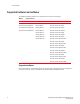
In this chapter Supported hardware and software The following hardware platforms are supported by this release of this guide: TABLE 1 Supported devices Brocade NetIron XMR Series Brocade MLX Series NetIron CES 2000 and NetIron CER 2000 Series Brocade NetIron XMR 4000 Brocade MLX-4 Brocade NetIron CES 2024C Brocade NetIron XMR 8000 Brocade MLX-8 Brocade NetIron CES 2024F Brocade NetIron XMR 16000 Brocade MLX-16 Brocade NetIron CES 2048C Brocade NetIron XMR 32000 Brocade MLX-32 Brocade NetIr
In this chapter Document conventions This section describes text formatting conventions and important notice formats used in this document.
In this chapter Notice to the reader This document may contain references to the trademarks of the following corporations. These trademarks are the properties of their respective companies and corporations. These references are made for informational purposes only.
In this chapter Getting technical help or reporting errors To contact Technical Support, go to http://www.brocade.com/services-support/index.page for the latest e-mail and telephone contact information.
In this chapter x Multi-Service IronWare Multicast Configuration Guide 53-1003032-02
Chapter 1 Configuring IP Multicast Protocols Table 2 displays the individual devices and the IP Multicast features they support.
1 Configuring IP Multicast Protocols TABLE 2 Supported IP Multicast features (Continued) Features supported Brocade NetIron XMR Brocade MLX Brocade Series NetIron CES 2000 Series BASE package Brocade NetIron CES 2000 Series ME_PREM package Brocade NetIron CES 2000 Series L3_PREM package Brocade NetIron CER 2000 Series Base package Brocade NetIron CER 2000 Series Advanced Services package PIM Sparse Yes Yes No Yes Yes Yes Yes PIM Multinet Yes Yes No Yes Yes Yes Yes Modifying the TT
Overview of IP multicasting 1 • Protocol Independent Multicast Dense mode (PIM DM) V1 (draft-ietf-pim-dm-05) and V2 (draft-ietf-pim-v2-dm-03) • PIM Sparse mode (PIM SM) V2 (RFC 2362) • Distance Vector Multicast Routing Protocol (DVMRP) V2 (RFC 1075) NOTE Each multicast protocol uses IGMP. IGMP is automatically enabled on an interface when you configure PIM or DVMRP, and is disabled on the interface if you disable PIM or DVMRP.
1 Changing global IP multicast parameters Changing global IP multicast parameters The following sections apply to PIM-DM, PIM-SM, IGMP, and DVMRP. Concurrent support for multicast routing and snooping Multicast routing and multicast snooping instances work concurrently on the same device. For example, you can configure PIM routing on certain VEs interfaces and snooping on other VEs or VLANs.
Changing global IP multicast parameters 1 Syntax: [no] max-mcache num The vrf parameter specified with the router dvmrp command allows you to configure the max-mcache command for a virtual routing instance (VRF) specified by the variable vrf-name. The num variable specifies the maximum number of multicast cache entries for DVMRP in the specified VRF.
1 Changing global IP multicast parameters The vrf parameter specified with the router pim command allows you to configure the max-mcache command for a virtual routing instance (VRF) specified by the variable vrf-name. The num variable specifies the maximum number of multicast cache entries for PIM in the specified VRF. If not defined by this command, the maximum value is determined by available system resources.
Changing global IP multicast parameters 1 The num variable specifies the maximum number of IGMP group addresses you want to make available for the default VRF. If not defined by this command, the maximum value is determined by available system resources. Changing IGMP V1 and V2 parameters IGMP allows Brocade devices to limit the multicast of IGMP packets to only those ports on the device that are identified as IP Multicast members.
1 Mtrace overview To define an IGMP (V1 and V2) membership time of 240 seconds, enter the following. Brocade(config)# ip igmp group-membership-time 240 Syntax: [no] ip igmp group-membership-time num The num variable specifies the number of seconds and can be a value from 5 - 26000. The default value is 260.
Mtrace overview 1 Multicast traceroute uses any information available to it in the router to determine a previous hop to forward the trace towards the source. Multicast routing protocols vary in the type and amount of state they keep; multicast traceroute endeavors to work with all of them by using whatever is available. For example, if a PIM-SM router is on the (*,G) tree, it chooses the parent towards the RP as the previous hop.
1 Mtrace overview Configuring mtrace To explain how mtrace works, let's take the network topology depicted inFigure 1 . The mtrace can be started on any router on the network. The format of the command to start a mtrace would be: Brocade#mtrace ipv6 source 102::1 destination 101::2 group ff1d::2 Mtrace handle query from src 102::1 to dest 101::2 through group ff1d::2 Collecting Statistics, waiting time 5 seconds.....
Support for Multicast Multi-VRF 1 Support for Multicast Multi-VRF Multicast Multi-VRF support for the Brocade device includes the following: • Static Mroute – As described in “Configuring a static multicast route within a VRF” you can configure static multicast route from within a specified VRF. • PIM (PIM-SM and PIM-DM) – The procedure for configuring PIM within a VRF instance is described in “Enabling PIM for a specified VRF” and “Enabling PIM Sparse for a specified VRF”.
1 Adding an interface to a multicast group • • • • • • • • “show ip dvmrp [vrf vrf-name] interface” “show ip dvmrp [vrf vrf-name] mcache” “clear ip igmp [ vrf vrf-name ] cache” “clear ip igmp [ vrf vrf-name ] traffic” “show ip igmp [vrf vrf-name] group group-address [detail] [tracking]” “show ip igmp [vrf vrf-name] interface [ve number | ethernet slot/port | tunnel num]” “show ip igmp [vrf vrf-name] settings” “show ip igmp [vrf vrf-name] traffic” Adding an interface to a multicast group You can manually
Multicast non-stop routing 1 Multicast non-stop routing Multicast non-stop routing (NSR) provides hitless upgrade and switchover support for all IPv4 multicast, including default and non-default VRFs for IPv4 PIM-DM, PIM-SM, and PIM-SSM. Multicast NSR is not supported for IPv6 multicast and DVMRP. The software multicast state is kept in sync between the active and standby MPs. As the Brocade system enters a hitless upgrade or switchover state, the standby MP will take over as the new active MP.
1 Multicast non-stop routing The syslog message displayed above shows the state transition of multicast NSR as the standby MP takes over as the active MP. The multicast data traffic will continue to flow during state transition. Displaying the multicast NSR status To display the multicast NSR status, enter the following command.
Passive Multicast Route Insertion (PMRI) TABLE 5 1 Output from the show ip pim counter nsr command This field... Displays... Mcache sync The mcache NSR sync queue that carries the NSR sync message for mcache updates. pack The number of NSR sync messages that are packed from current MP to the other MP. unpack The number of NSR sync messages that are received and unpacked by the current MP. ack The number of NSR sync acknowledgement the current MP received.
1 IP multicast boundaries Configuring PMRI PMRI is enabled by default. To disable PMRI, enter commands such as the following. Brocade(config)# router pim Brocade(config-pim-router)# hardware-drop-disable Syntax: [no] hardware-drop-disable Displaying hardware-drop Use the show ip pim sparse command to display if the hardware-drop feature has been enabled or disabled.
IP multicast boundaries 1 Configuring multicast boundaries Multicast boundaries can be configured for IPv4 or IPv6. To define boundaries for PIM enabled interfaces, enter a commands such as the following. Brocade(config)# interface ve 40 Brocade(config-vif-40)#ip multicast-boundary MyBrocadeAccessList Multicast boundaries can be configured for IPv6 as shown in the following.
1 IP multicast boundaries ---------+-------------+----+---+------------------+---+---------+-------+------Interface|Local |Mode|Ver|Designated Router |TTL|Multicast| VRF | DR |Address | | |Address Port|Thr|Boundary | | Prio ---------+-------------+----+---+------------------+---+---------+-------+------v10 10.1.2.1 SM V2 Itself 1 None default 30 v30 123.1.1.2 SM V2 Itself 1 None v40 124.1.1.
IP multicast boundaries 1 This feature is useful when the core is running MPLS and multicast routing protocols (like GRE MVPN). There can be an IGP shortcut path or LSP path which would provide next-hop as the tunnel interface. The IGPs can route unicast traffic over these tunnels to destinations that are downstream from the egress router of the tunnel. Without this feature, RPF path through LSP cannot be directly used to send PIM control packets.
1 IP multicast boundaries If this feature is disabled, configuration will be removed from multicast and if the native route changes then the RPF for the multicast cache entries would change. Further, RPF lookup after disabling this feature will not use LSP's underlying native path as RPF path. If RPF lookup results in non-LSP multicast enabled path, RPF would resolve or else RPF resolution would fail.
IP multicast boundaries 1 Figure 3 shows a topology in which R1 through R11 have IP addresses in ascending order i.e. R1 having the lowest ip address and R11 having the highest. All the routers are PIM enabled routers. The links emanating from each router are ECMP links. The existing behavior path utilization is indicated in red. With the highest IP address neighbor chosen for the ECMP paths available, the multicast cache entries get to utilize only the R1-R4-R11-SRC/RP path.
1 IP multicast boundaries Hash based load Distribution • • • • • Depends on a hash function to distribute the multicast cache entries. hash function based S, G, next-hop addresses. Splits the cache entries by choosing a different RPF neighbor and in turn splits the traffic. Load balancing is based on the distribution of the keys S, G, next-hop. Least disruptive as the hashing redistributes only those cache entries that are affected during link flaps.
IP multicast boundaries 1 • If the rebalancing is not configured, then link flap results in sub-optimal utilization of the ECMP links. • The number of paths supported by multicast ECMP would be the same as unicast ECMP which is 32. Enabling Multicast ECMP The ip multicast-routing load-sharing command configures the hash based distribution among the ECMP paths. Once configured, this redistributes the existing flows among the available ECMP paths.
1 PIM Dense If the group address is not specified and there are multiple paths to the unicast address mentioned then the multiple ECMP upstream neighbors will be shown. Brocade(config)# show ip pim vrf eng rpf 130.50.11.10 Upstream Nbr Phy Port 55.55.55.55 e4/1 66.55.55.55 e4/2 Brocade(config)# show ip pim mcache load-sharing src-ip-address Brocade(config)# show ip pim mcache load-sharing 130.50.11.10 Source/RP Address Upstream Nbr Interface Count 130.50.11.10 55.55.55.55 e4/1 4 130.50.11.10 66.55.55.
PIM Dense 1 In Figure 5, the root node (R1) is forwarding multicast packets for group 229.225.0.1, which it receives from the server, to its downstream nodes, R2, R3, and R4. Device R4 is an intermediate device with R5 and R6 as its downstream devices. Because R5 and R6 have no downstream interfaces, they are leaf nodes. The receivers in this example are those workstations that are resident on devices R2, R3, and R6.
1 PIM Dense FIGURE 6 26 Pruning leaf nodes from a multicast tree Multi-Service IronWare Multicast Configuration Guide 53-1003032-02
PIM Dense 1 Grafts to a multicast tree A PIM device restores pruned branches to a multicast tree by sending graft messages towards the upstream device. Graft messages start at the leaf node and travel up the tree, first sending the message to its neighbor upstream device. In the example above, if a new 229.255.0.1 group member joins on device R6, which was previously pruned, a graft is sent upstream to R4. Since the forwarding state for this entry is in a prune state, R4 sends a graft to R1.
1 PIM Dense The CLI commands for configuring and managing PIM DM are the same for V1 and V2. The only difference is the command you use to enable the protocol on an interface. NOTE If you want to continue to use PIM DM V1 on an interface, you must change the version, then save the configuration. NOTE The note above does not mean you can run different PIM versions on devices that are connected to each other. The devices must run the same version of PIM.
PIM Dense 1 Enabling PIM for a specified VRF To enable PIM for the VRF named “blue”, use the following commands. Brocade(config)# router pim vrf blue Syntax: [no] router pim [vrf vrf-name] The vrf parameter allows you to configure PIM (PIM-DM and PIM-SM) on the virtual routing instance (VRF) specified by the vrf-name variable. All PIM parameters available for the default device instance are configurable for a VRF-based PIM instance.
1 PIM Dense The interval can be set between 3 and 65535 seconds, and it should not be less than 3.5 times the hello timer value. The default value is 105 seconds. To apply a PIM neighbor timeout value of 360 seconds to all ports on the device operating with PIM, enter the following. Brocade(config)# router pim Brocade(config-pim-router)# nbr-timeout 360 Syntax: [no] nbr-timeout seconds The default is 105 seconds. The range is 3-65535 seconds.
PIM Dense 1 A prune wait value of zero causes the PIM device to stop traffic immediately upon receiving a prune message. If there are two or more neighbors on the physical port, then the prune-wait command should not be used because one neighbor may send a prune message while the other sends a join message at the same time, or within less than three seconds. To set the prune wait time to zero, enter the following commands.
1 PIM Dense Total number of IP routes: 19 Type Codes - B:BGP D:Connected I:ISIS S:Static R:RIP O:OSPF Cost - Dist/Metric Destination Gateway Port Cost Type .. 172.17.41.4 137.80.127.3 v11 2 O 172.17.41.4 137.80.126.3 v10 2 O 172.17.41.4 137.80.129.1 v13 2 O 172.17.41.4 137.80.128.3 v12 2 O 172.17.41.8 0.0.0.
PIM Dense 1 1. If more than one device has the same DR priority on a subnet (as in the case of default DR priority on all), the device with the numerically highest IP address on that subnet is elected as the DR. 2. The DR priority information is used in the DR election ONLY IF ALL the PIM devices connected to the subnet support the DR priority option.
1 PIM Dense This field... Displays... Join or Prune interval How long a PIM device will maintain a prune state for a forwarding entry. Prune Age The number of packets the device sends using the path through the RP before switching to using the SPT path. Hardware Drop Enabled Displays Yes if the Passive Multicast Route Insertion feature is enable and No if it is not. Prune Wait Interval The amount of time a PIM device waits before stopping traffic to neighbor devices that do not want the traffic.
PIM Dense 1 e2/2,2/2(150) 8 (104.1.1.2 231.0.1.5): e2/2,2/2(150) 9 (108.1.1.100 231.0.1.5): e2/2,2/2(150) Total Prune entries: 9 Syntax: show ip pim [ vrf vrf-name ] prune Displaying all multicast cache entries You can use the following command to display all multicast cache entries. Brocade(config)# show ip pim mcache Total entries in mcache: 234 1 (104.1.1.2, 231.0.1.1) in v102 (tag e1/19), Uptime 00:02:15 Rate 0 upstream neighbor=102.1.1.
1 PIM Dense TABLE 6 36 Output fields from the show ip pim mcache command Field Description Total entries in mcache Shows the total number of PIM mcache entries MJ Membership Join MI Membership Include ME Membership Exclude - Legend for the mcache entry printed once per page, it gives the explanation of each of the flags used in the entry. BR Blocked RPT BA Blocked Assert BF Blocked Filter BI Blocked IIF Uptime Shows the software entry uptime.
PIM Dense 1 Field Description RegPkt Shows the number of packets forwarded due to the Register decapsulation. This field is displayed only on the MP module. This field displays only those entries for which the device is the RP. However, for a PIM DM entry the RegPkt field is not displayed for the (S,G) entries on the MP module. AvgRate Shows the average rate of packets ingressing for this entry over a 30 second period.
1 PIM Dense You can use the following command to filter the output to display only the Dense Mode routes in the mcache. Brocade#show ip pim mcache dense You can use the following command to filter the output to display only the entries matching a specific source. Brocade#show ip pim mcache 1.1.1.1 You can use the following command to filter the output to display only the entries matching a specific group. Brocade#show ip pim mcache 239.1.1.
PIM Dense 1 Limitation and prerequisites Following are the behavior of ACL which affect PIM-neighbor filtering process. 1. All ACLs have an implicit deny all clause unless overridden by an explicit permit all clause. Brocade devices override it for an ACL without any clauses.When you apply an empty ACL to an interface, one without any clauses, it allows all traffic on the interface to pass through without filtering. 2. There are no checks to validate if an ACL applied to an interface already exists.
1 PIM Sparse no version of the command removes the neighbor filtering applied on that interface, if any. It is not mandatory to provide Access-list name or number as at most only one ACL can be applied per interface. Displaying show command These commands will display the configuration. Brocade(config)#show run ! interface ethernet 1/3 enable ip address 10.10.10.
PIM Sparse 1 PIM Sparse device types Devices that are configured with PIM Sparse interfaces also can be configured to fill one or more of the following roles: • PMBR – A PIM device that has some interfaces within the PIM domain and other interface outside the PIM domain. PBMRs connect the PIM domain to the Internet. • BSR – The Bootstrap Router (BSR) distributes RP information to the other PIM Sparse devices within the domain. Each PIM Sparse domain has one active BSR.
1 PIM Sparse RP paths and SPT paths Figure 8 shows two paths for packets from the source for group 239.255.162.1 and a receiver for the group. The source is attached to PIM Sparse device A and the recipient is attached to PIM Sparse device C. PIM Sparse device B in is the RP for this multicast group. As a result, the default path for packets from the source to the receiver is through the RP. However, the path through the RP sometimes is not the shortest path.
PIM Sparse 1 Configuring global PIM Sparse parameters To configure basic global PIM Sparse parameters, enter commands such as the following on each Brocade device within the PIM Sparse domain. Brocade(config)# router pim Syntax: [no] router pim NOTE You do not need to globally enable IP multicast routing when configuring PIM Sparse. The command in this example enables IP multicast routing, and enables the PIM Sparse mode of IP multicast routing.
1 PIM Sparse Syntax: [no] ip pim border Configuring BSRs In addition to the global and interface parameters described in the previous sections, you need to identify an interface on at least one device as a candidate PIM Sparse Bootstrap router (BSR) and candidate PIM Sparse Rendezvous Point (RP). NOTE It is possible to configure the device as only a candidate BSR or RP, but it is recommended that you configure the same interface on the same device as both a BSR and an RP.
PIM Sparse 1 • Enter ve num for a virtual interface. • Enter loopback num for a loopback interface. • Enter tunnel num for a GRE tunnel interface to be configured. The GRE tunnel interface is enabled under the router PIM configuration. By default, this command configures the device as a candidate RP for all group numbers beginning with 224. As a result, the device is a candidate RP for all valid PIM Sparse group numbers. You can change this by adding or deleting specific address ranges.
1 PIM Sparse The clear pim rp-map command allows you to update the entries in the static multicast forwarding table immediately after making RP configuration changes. This command is meant to be used with rp-address command. To update the entries in a PIM sparse static multicast forwarding table with new RP configuration, enter the following command at the privileged EXEC level of the CLI.
PIM Sparse 1 Configuration considerations: • The Static RP has higher precedence over RP learnt from the BSR. • There is a limit of 64 static RPs in the systems. Configuring an ACL based RP assignment To configure an ACL based RP assignment, enter commands such as the following. Brocade(config)# router pim Brocade(config-pim-router)# rp-address 130.1.1.
1 PIM Sparse Configuring route precedence by specifying route types The route precedence command lets you control the selection of routes based on the following route types: • • • • Non-default route from the mRTM Default route from the mRTM Non-default route from the uRTM Default route from the uRTM Use this command to specify an option for all of the precedence levels.
PIM Sparse 1 ---------+---------------+----+---+---------------------+---+---------+-------+------+---------+ Interface|Local |Ver |St | Designated Router |TTL|Multicast| VRF | DR | Override |Address | | |Address Port|Thr|Boundary | | Prio | Interval ---------+---------------+----+---+---------------------+---+---------+-------+------+---------+ v3 3.1.1.2 SMv2 Ena Itself 1 None default 1 3000ms v4 4.1.1.2 SMv2 Ena Itself 1 None default 1 3000ms v10 10.1.1.1 SMv2 Ena Itself 1 None default 1 3000ms v12 12.
1 PIM Sparse The infinity | num parameter specifies the number of packets. If you specify infinity, the device sends packets using the RP indefinitely and does not switch over to the SPT. If you enter a specific number of packets, the device does not switch over to using the SPT until it has sent the number of packets you specify using the RP. Configuring PIM-SM (*,g) forwarding By default, the device supports only (s,g) hardware routing.
Multicast Outgoing Interface (OIF) list optimization 1 The num parameter specifies the number of seconds and can from 10 – 65535. The default is 60. PIM multinet Brocade devices support PIM over secondary addresses in IPv4. Whenever a secondary address is configured on a interface, all the secondary addresses configured on the interface are sent out on the PIM Hello using the secondary address option.
1 Multicast Outgoing Interface (OIF) list optimization Displaying PIM Sparse configuration information and statistics You can display the following PIM Sparse information: • • • • • • • • • • • • Basic PIM Sparse configuration information Group information BSR information Candidate RP information RP-to-group mappings RP information for a PIM Sparse group RP set list PIM neighbor information The PIM flow cache The PIM multicast cache PIM traffic statistics PIM counter statistics Displaying basic PIM Spa
Multicast Outgoing Interface (OIF) list optimization 1 Table 8 shows the information displayed by the show ip pim sparse command. TABLE 8 Output of the show ip pim sparse command This field... Displays... Global PIM Sparse mode settings Hello interval How frequently the device sends PIM Sparse hello messages to its PIM Sparse neighbors. This field also shows the number of seconds between hello messages. PIM Sparse devices use hello messages to discover each another.
1 Multicast Outgoing Interface (OIF) list optimization TABLE 8 Output of the show ip pim sparse command (Continued) This field... Displays... TTL Threshold Following the TTL threshold value, the interface state is listed. The interface state can be one of the following: • Disabled • Enabled Local Address Indicates the IP address configured on the port or virtual interface.
Multicast Outgoing Interface (OIF) list optimization TABLE 9 1 Output from the show ip pim vrf group command (Continued) This field... Displays... Group The multicast group address Ports The device ports connected to the receivers of the groups. Displaying BSR information To display BSR information, enter the following command at any CLI level.
1 Multicast Outgoing Interface (OIF) list optimization TABLE 10 Output from the show ip pim bsr command This field... Displays... BSR address The IP address of the interface configured as the PIM Sparse Bootstrap Router (BSR). Uptime The amount of time the BSR has been running. NOTE: This field appears only if this device is the BSR. BSR priority The priority assigned to the interface for use during the BSR election process.
Multicast Outgoing Interface (OIF) list optimization 1 Table 11 describes the output from this command. TABLE 11 Output from the show ip pim rp-candidate command This field... Displays... Candidate-RP-advertisement in Indicates how many seconds will pass before the BSR sends the next RP message. NOTE: This field appears only if this device is a candidate RP. RP Indicates the IP address of the Rendezvous Point (RP). NOTE: This field appears only if this device is a candidate RP.
1 Multicast Outgoing Interface (OIF) list optimization The vrf option allows you to display RP information for the VRF instance identified by the vrf-name variable. The group-addr parameter is the address of a PIM Sparse IP multicast group. Table 13 describes the output from this command. TABLE 13 Output from the show ip pim command This field... Displays...
Multicast Outgoing Interface (OIF) list optimization TABLE 14 1 Output from the show ip pim vrf rp-set command (Continued) This field... Displays... priority The RP priority of the candidate RP. During the election process, the candidate RP with the highest priority is elected as the RP. age The age (in seconds) of this RP-set. NOTE: If this device is not a BSR, this field contains zero. Only the BSR ages the RP-set.
1 Multicast Outgoing Interface (OIF) list optimization Displaying the PIM multicast cache To display the PIM multicast cache, enter the following command at any CLI level. Brocade(config)# show ip pim mcache 54.1.1.10 226.0.1.
Multicast Outgoing Interface (OIF) list optimization TABLE 16 1 Output fields from the show ip pim mcache command Field Description Total entries in mcache Shows the total number of PIM mcache entries MJ Membership Join MI Membership Include ME Membership Exclude - Legend for the mcache entry printed once per page, it gives the explanation of each of the flags used in the entry.
1 Multicast Outgoing Interface (OIF) list optimization Field Description Number of matching entries Shows the total number of mcache entries matching a particular multicast filter specified. Outgoing interfaces Section This section consists of three parts. L3 OIFs, L2OIFs and Blocked OIFs. And each section has Format of L3/L2/Blocked followed by (HW/SW) followed by count of the number of OIF in each section. Additionally, each section displays the OIFs one per line.
Multicast Outgoing Interface (OIF) list optimization 1 L3 (HW) 1: e4/12(VL52) Flags (0x7046c8e1) sm=1 ssm=0 hw=1 fast=1 slow=0 leaf=0 prun=0 tag=1 needRte=0 msdp_adv=1 AgeSltMsk=00000008, FID: 0x800e MVID: 1 , RegPkt 0, AvgRate 11257 profile: none 3 (49.1.1.108, 229.0.0.2) in v49 (tag e4/9), Uptime 00:03:51 Rate 11257 Sparse Mode, RPT=0 SPT=1 Reg=0 L2Reg=1 RegSupp=0 RegProbe=0 LSrc=1 LRcv=1 Source is directly connected. RP 192.168.1.
1 Multicast Outgoing Interface (OIF) list optimization TABLE 17 Output parameters of the show ip pim mcache mvid 1 command (Continued) Field Description fast ports ethe Shows the forwarding port ID. L3 Show whether the traffic is switched or routed out of the interface. (HW) Show whether the entry is software forwarded or hardware forwarded. sm Sets the flag to 1, if the Sparse Mode entry is enabled and 0, if the PIM dense mode entry is enabled.
Multicast Outgoing Interface (OIF) list optimization 1 sm=1 ssm=0 hw=1 fast=1 slow=0 leaf=0 prun=0 tag=1 needRte=0 msdp_adv=1 AgeSltMsk=00000008, FID: 0x800e MVID: 1 , RegPkt 0, AvgRate 0 profile: none 2 (49.1.1.108, 229.0.0.1) in v49 (tag e4/9), Uptime 00:03:32 Rate 11257 Sparse Mode, RPT=0 SPT=1 Reg=0 L2Reg=1 RegSupp=0 RegProbe=0 LSrc=1 LRcv=1 Source is directly connected. RP 192.168.1.
1 Multicast Outgoing Interface (OIF) list optimization TABLE 18 Output parameters of the show ip pim mcache fid 8 command (Continued) Field Description RP Show the IP address of the RP. num_oifs Show the count of the outgoing interfaces. inherited_oifs Show the PIM Sparse mode inherited outgoing interfaces. blocked_oifs Show the PIM Sparse mode blocked outgoing interfaces. Flags Show the flags associated with the forward entry. fast ports ethe Shows the forwarding port ID.
Multicast Outgoing Interface (OIF) list optimization 1 Clearing the PIM forwarding cache You can clear the PIM forwarding cache using the following command. Brocade# clear ip pim cache Syntax: clear ip pim [ vrf vrf-name ] cache Use the vrf option to clear the PIM forwarding cache for a VRF instance specified by the vrf-name variable. Displaying PIM traffic statistics To display PIM traffic statistics, enter the following command at any CLI level.
1 Multicast Outgoing Interface (OIF) list optimization TABLE 19 Output from the show ip pim vrf traffic command This field... Displays... Port The port or virtual interface on which the PIM interface is configured. Hello The number of PIM Hello messages sent or received on the interface. J or P The number of Join or Prune messages sent or received on the interface. NOTE: Unlike PIM dense, PIM Sparse uses the same messages for Joins and Prunes.
1 Configuring Multicast Source Discovery Protocol (MSDP) S_G_AGEOUT : ABOVE_THRESHOLD : 0 255 MP to LP IPCs: INIT DELETE_VPORT MOVE_VPORT INSERT_SOURCE RESET_SRC_LIST AGE_RESET OIF_FLAG_CHANGE : : : : : : : 2317 255 0 0 0 94924 741 Error Counters: RPSET_MAXED : 0 WRONG_IF : MCAST_FIRST_DATA : INSERT_VPORT DELETE_VIF DEL_ENTRY DELETE_SOURCE MOVE_TNNL_PORT FLAG_CHANGE : : : : : : 378153 765 4465 255 510 0 0 741 Brocade(config)# Syntax: show ip pim [vrf vrf-name] counter Table 20 describes the
1 Configuring Multicast Source Discovery Protocol (MSDP) In this example, the source for PIM Sparse multicast group 232.0.1.95 is in PIM Sparse domain 1. The source sends a packet for the group to its directly attached DR. The DR sends a Group Advertisement message for the group to the RP for the domain. The RP is configured for MSDP, which enables the RP to exchange source information with other PIM Sparse domains by communicating with RPs in other domains that are running MSDP.
Configuring Multicast Source Discovery Protocol (MSDP) 1 The MSDP device in domain 2 does not forward the Source Active back to the peer in domain 1, because that is the peer from which the device received the message. An MSDP device never sends a Source Active message back to the peer that sent it. The peer that sent the message is sometimes called the “RPF peer”.
1 Configuring Multicast Source Discovery Protocol (MSDP) Enabling MSDP for a specified VRF The vrf parameter allows you to configure MSDP on the virtual routing instance (VRF) specified by the vrf-name variable. All MSDP parameters available for the default router instance are configurable for a VRF-based MSDP instance. To enable MSDP for the VRF named “blue”, enter the following commands.
Configuring Multicast Source Discovery Protocol (MSDP) 1 Syntax: [no] msdp-peer ip-addr shutdown The ip-addr parameter specifies the IP address of the MSDP peer that you want to disable. Designating the interface IP address as the RP IP address When an RP receives a Source Active message, it checks its PIM Sparse multicast group table for receivers for the group. If a receiver exists the RP sends a Join to the source.
1 Configuring Multicast Source Discovery Protocol (MSDP) • For peer 2.2.2.99, all source-group pairs in Source-Active messages from the neighbor are filtered (dropped). • For peer 2.2.2.97, all source-group pairs except those with source address matching 10.x.x.x and group address of 235.10.10.1 are permitted. • For peer 2.2.2.96, all source-group pairs except those associated with RP 2.2.42.3 are permitted.
Configuring Multicast Source Discovery Protocol (MSDP) 1 • sa-filter in 2.2.2.96 route-map msdp2_map rp-route-map msdp2_rp_map – This command accepts all source-group pairs except those associated with RP 2.2.42.3. Syntax: [no] sa-filter in | originate | out ip-addr [route-map map-tag] [rp-route-map rp-map-tag] Selecting the in option applies the filter to incoming Source-Active messages. Selecting the originate option applies the filter to self-originated outbound Source-Active messages.
1 Configuring Multicast Source Discovery Protocol (MSDP) NOTE The default filter action is deny. If you want to permit some source-group pairs, use a route map. A permit action in the route map allows the device to advertise the matching source-group pairs. A deny action in the route map drops the source-group pairs from advertisements.
Configuring Multicast Source Discovery Protocol (MSDP) 1 Brocade# show ip msdp vrf blue peer Total number of MSDP Peers: 2 1 IP Address 206.251.17.
1 Configuring Multicast Source Discovery Protocol (MSDP) TABLE 22 MSDP peer information (Continued) This field... Displays... Notifications Received The number of notification messages the MSDP device has received from the peer. Source-Active Sent The number of source active messages the MSDP device has sent to the peer. Source-Active Received The number of source active messages the MSDP device has received from the peer.
Configuring Multicast Source Discovery Protocol (MSDP) TABLE 22 1 MSDP peer information (Continued) This field... Displays... TCP connection state The state of the connection with the neighbor. Can be one of the following: • LISTEN – Waiting for a connection request. • SYN-SENT – Waiting for a matching connection request after having sent a connection request. • SYN-RECEIVED – Waiting for a confirming connection request acknowledgment after having both received and sent a connection request.
1 Configuring Multicast Source Discovery Protocol (MSDP) Displaying Source Active cache information To display the Source Actives in the MSDP cache, use the following command. Brocade# show ip msdp vrf blue sa-cache Total of 10 SA cache entries Index RP address (Source, Group) 1 2.2.2.2 (192.6.1.10, 227.1.1.1) 2 2.2.2.2 (192.6.1.10, 227.1.1.2) 3 2.2.2.2 (192.6.1.10, 227.1.1.3) 4 2.2.2.2 (192.6.1.10, 227.1.1.4) 5 2.2.2.2 (192.6.1.10, 227.1.1.5) 6 2.2.2.2 (192.6.1.10, 227.1.1.6) 7 2.2.2.2 (192.6.1.10, 227.
Configuring Multicast Source Discovery Protocol (MSDP) 1 You can use the following command to filter the output to display only the SA cache entries that are received from peers in the BGP AS Number 100. Brocade#show ip msdp sa-cache 100 You can use the following command to filter the output to display only the SA cache entries that are originated by the RP 1.1.1.1. Brocade#show ip msdp sa-cache orig-rp 1.1.1.
1 Configuring Multicast Source Discovery Protocol (MSDP) In Out In 40.40.40.2 Out 1001 ESTABLISH 5569 5568 0 0 Out 0 In 0 57 Syntax: show ip msdp vrf VRF-name rpf-peer ip-addr Clearing MSDP information You can clear the following MSDP information: • Peer information • Source active cache • MSDP statistics Clearing peer information To clear MSDP peer information, enter the following command at the Privileged EXEC level of the CLI. Brocade# clear ip msdp peer 205.216.162.
Configuring MSDP mesh groups 1 Clearing MSDP VRF statistics To clear the MSDP VRF statistics by entering the following command. Brocade# clear ip msdp vrf blue statistics Syntax: clear ip msdp statistics [vrf vrf-name] [ip-addr] The command in this example clears statistics for all the peers. To clear statistics for only a specific peer, enter the IP address of the peer. The command in this example clears all statistics for all the peers in the VRF “blue.”.
1 Configuring MSDP mesh groups PIM Sparse Domain 1 in Figure 10 contains a mesh group with four RPs. When the first RP, for example, RP 206.251.21.31 originates or receives an SA message from a peer in another domain, it sends the SA message to its peers within the mesh group. However, the peers do not send the message back to the originator RP or to each other. The RPs then send the SA message farther away to their peers in other domains.
MSDP Anycast RP 1 The sample configuration above reflects the configuration in Figure 10. On RP 206.251.21.31 you specify its peers within the same domain (206.251.18.31, 206.251.19.31, and 206.251.20.31). You first configure the MSDP peers using the msdp-peer command to assign their IP addresses and the loopback interfaces. Next, place the MSDP peers within a domain into a mesh group. Use the mesh-group command. There are no default mesh groups. The group-name parameter identifies the mesh group.
1 MSDP Anycast RP NOTE The anycast RP address *must* not be the IGP router-id. • Enable PIM-SM on all interfaces on which multicast routing is desired. • Enable an IGP on each of the loopback interfaces and physical interfaces configured for PIM-SM. • Configure loopback interfaces with unique IP addresses on each of the RPs for MSDP peering. This loopback interface is also used as the MSDP originator-id.
MSDP Anycast RP 1 RP 1 configuration The following commands provide the configuration for the RP 1 router. RP1(config)#router ospf RP1(config-ospf-router)# area 0 RP1(config-ospf-router)# exit RP1(config)# interface loopback 1 RP1(config-lbif-1)# ip ospf area 0 RP1(config-lbif-1)# ip ospf passive RP1(config-lbif-1)# ip address 10.0.0.
1 MSDP Anycast RP RP2(config)# interface ethernet 5/2 RP2(config-if-e1000-5/2)# ip ospf area 0 RP2(config-if-e1000-5/2)# ip ospf cost 5 RP2(config-if-e1000-5/2)# ip address 192.5.2.1/24 RP2(config-if-e1000-5/2)# ip pim-sparse RP2(config)# interface ethernet 5/3 RP2(config-if-e1000-5/3)# ip ospf area 0 RP2(config-if-e1000-5/3)# ip ospf cost 10 RP2(config-if-e1000-5/3)# ip address 192.6.1.
PIM Anycast RP 1 PIMR2(config)# router pim PIMR2(config-pim-router)# rp-address 10.0.0.1 PIMR2(config-pim-router)# exit PIM Anycast RP PIM Anycast RP is a method of providing load balancing and fast convergence to PIM RPs in an IPv4 multicast domain. The RP address of the Anycast RP is a shared address used among multiple PIM routers, known as PIM RP. The PIM RP routers create an Anycast RP set.
1 PIM Anycast RP Brocade(config-pim-router)#ip access-list standard my-anycast-rp-set Brocade(config-std-nacl)#permit host 1.1.1.1 Brocade(config-std-nacl)#permit host 2.2.2.2 Brocade(config-std-nacl)#permit host 3.3.3.3 The RP shared address 100.1.1.1 is used in the PIM domain. IP addresses 1.1.1.1, 2.2.2.2, and 3.3.3.3 are listed in the ACL that forms the self inclusive Anycast RP set. Multiple anycast-rp instances can be configured on a system; each peer with the same or different Anycast RP set.
DVMRP overview TABLE 24 1 Display of show ip pim-anycast-rp This field... Displays... Number of Anycast RP: The Number of Anycast RP specifies the number of Anycast RP sets in the multicast domain. Anycast RP: The Anycast RP address specifies a shared RP address used among multiple PIM routers. ACL ID: The ACL ID specifies the ACL ID assigned. ACL Name The ACL Name specifies the name of the Anycast RP set. ACL Filter The ACL Filter specifies the ACL filter state SET or UNSET.
1 DVMRP overview In Figure 13, the root node (R1) is forwarding multicast packets for group 229.225.0.2 that it receives from the server to its downstream nodes, R2, R3, and R4. Router R4 is an intermediate router with R5 and R6 as its downstream routers. Because R5 and R6 have no downstream interfaces, they are leaf nodes. The receivers in this example are those workstations that are resident on routers R2, R3, and R6.
Configuring DVMRP 1 Grafts to a multicast tree A DVMRP router restores pruned branches to a multicast tree by sending graft messages towards the upstream router. Graft messages start at the leaf node and travel up the tree, first sending the message to its neighbor upstream router. In the example above, if a new 229.255.0.1 group member joins on router R6, which had been pruned previously, a graft will be sent upstream to R4.
1 Configuring DVMRP DVMRP is enabled on each of the Brocade devices, shown in Figure 13, on which multicasts are expected. You can enable DVMRP on each Brocade device independently or remotely from one Brocade device by a Telnet connection. Follow the same steps for each router. Globally enabling and disabling DVMRP To globally enable DVMRP, enter the following command.
Configuring DVMRP 1 • Report interval • Trigger interval • Default route Modifying neighbor timeout The neighbor timeout specifies the period of time that a router will wait before it defines an attached DVMRP neighbor router as down. Possible values are 60 – 8000 seconds. The default value is 180 seconds. To modify the neighbor timeout value to 100, enter the following. Brocade(config-dvmrp-router)# nbr 100 Syntax: [no] nbr-timeout 40-8000 The default is 105 seconds. The range is 35-65535 seconds.
1 Configuring DVMRP Subsequent retransmissions are sent at an interval twice that of the preceding interval. Possible values are from 5 – 3600 seconds. The default value is 10 seconds. To modify the setting for graft retransmit time to 120, enter the following. Brocade(config-dvmrp-router)# graft 120 Syntax: [no] graft-retransmit-time 5-3600 Modifying probe interval The Probe Interval defines how often neighbor probe messages are sent to the ALL-DVMRP-ROUTERS IP multicast group address.
Configuring DVMRP 1 Modifying DVMRP interface parameters DVMRP global parameters come with preset values. The defaults work well in most networks, but you can modify the following interface parameters if you need to: • TTL Threshold • Metric • Advertising Modifying the TTL threshold The TTL defines the minimum value required in a packet in order for the packet to be forwarded out the interface.
1 Configuring DVMRP • • • • • DVMRP neighbor information DVMRP active prune information Available multicast resources IP multicast route information Active multicast traffic information Displaying DVMRP group information To display DVMRP group information, enter the following command. Brocade# show ip dvmrp group Total number of groups: 2 1 Group 225.1.1.1 Ports Group member at e2/3: v30 2 Group 226.1.1.
Configuring DVMRP Interface e8/1 TTL Threshold: Local Address: DR: itself Interface v10 TTL Threshold: Local Address: DR: itself Interface v20 TTL Threshold: Local Address: DR: itself Interface v30 TTL Threshold: Local Address: DR: itself Interface v40 TTL Threshold: Local Address: DR: itself 1 1, Enabled, Querier 172.8.1.1 1, Enabled, Querier 192.1.1.1 logical Vid=1 1, Enabled, Querier 192.2.1.1 logical Vid=2 1, Enabled, Querier 192.3.1.1 logical Vid=3 1, Enabled, Querier 192.4.1.
1 Configuring DVMRP fast ports ethe 3/1 to 3/2 AgeSltMsk=00000004, FID: 0x800e, MVID: 30 profile: none Forwarding_oif: 2 L3 (HW) 2: TR(e3/1,e3/1)(VL20), 00:06:24/0, Flags: IM e3/2(VL1 ), 00:06:24/0, Flags: IM Syntax: show ip dvmrp [vrf vrf-name] mcache The vrf option allows you to display DVMRP Multicast cache information for the VRF instance identified by the vrf-name variable The display shows the following information TABLE 26 100 Output from the show ip dvmrp mcache command Field Description To
Configuring DVMRP TABLE 26 1 Output from the show ip dvmrp mcache command Field Description AvgRate Shows the average Rate of packets ingressing for this entry over 30 seconds. Profile Shows the Profile ID associated with the Stream. Number of matching entries Shows the total number of mcache entries matching a particular multicast filter specified. Outgoing interfaces Section This section consists of three parts. L3 OIFs, L2OIFs and Blocked OIFs.
1 Configuring DVMRP This field... Displays... Neighbor The IP address of the DVMRP neighbor. GenId The neighbor’s generation ID. Age The minimum time remaining before this DVMRP neighbor is aged out. UpTime The time in seconds that the DVMRP neighbor has been up. Displaying DVMRP active prune information To display DVMRP Active Prune information, enter the following command. Brocade# show ip dvmrp prune Port SourceNet Group Nbr e5/2 e5/2 172.5.1.1 172.5.1.1 192.2.1.2 192.1.1.2 226.1.1.
Configuring DVMRP 1 Syntax: show ip dvmrp [vrf vrf-name] resource The vrf option allows you to display available multicast resources for the VRF instance identified by the vrf-name variable. Displaying IP multicast route Information To display IP multicast route information, enter the following command. Brocade# show ip dvmrp route P:Parent M:Metric Total Routes=10 SourceNet Mask Gateway 100.1.1.0 Int e5/2 101.1.1.0 Int e5/2 102.1.1.0 Int e5/2 103.1.1.0 Int e5/2 172.5.1.2 172.5.1.2 172.5.1.2 172.5.1.
1 Configuring DVMRP The vrf option allows you to display multicast traffic information for the VRF instance identified by the vrf-name variable. The display shows the following information. This field... Displays... Port The port or virtual interface on which the PIM interface is configured. Probe The number of received, transmitted, and discarded probe messages. Graft The number of received, transmitted, and discarded graft messages.
Configuring DVMRP 1 The report shows the following information: This field Displays Version The DVMRP version operating on the router. Probe Interval The frequency in seconds at which neighbor probe messages are sent to the ALL-DVMRP-ROUTERS IP multicast group address. Possible values are 5 to 30 seconds. The default value is 10 seconds. This parameter is configured in “Modifying probe interval”.
1 Configuring a static multicast route Configuring a static multicast route Static multicast routes allow you to control the network path used by multicast traffic. Static multicast routes are especially useful when the unicast and multicast topologies of a network are different. You can avoid the need to make the topologies similar by instead configuring static multicast routes. NOTE This feature is not supported for DVMRP. You can configure more than one static multicast route.
Configuring a static multicast route 1 The distance parameter sets the administrative distance. This parameter is used by the software to determine the best path for the route. Thus, to ensure that the Brocade uses the default static route, assign a low administrative distance value. When comparing multiple paths for a route, the Brocade prefers the path with the lower administrative distance.
1 IGMP V3 To add a static route to a virtual interface, enter commands such as the following. Brocade(config)# ip mroute 0.0.0.0 0.0.0.0 ve 1 distance 1 Brocade(config)# write memory IGMP V3 The Internet Group Management Protocol (IGMP) allows an IPv4 system to communicate IP Multicast group membership information to its neighboring routers.
IGMP V3 1 • A “General Query” is sent by a multicast router to learn the complete multicast reception state of the neighboring interfaces. In a General Query, both the Group Address field and the Number of Sources (N) field are zero. • A “Group-Specific Query” is sent by a multicast router to learn the reception state, with respect to a *single* multicast address, of the neighboring interfaces.
1 IGMP V3 Compatibility with IGMP V1 and V2 Different multicast groups, interfaces, and routers can run their own version of IGMP. Their version of IGMP is reflected in the membership reports that the interfaces send to the router. Routers and interfaces must be configured to recognized the version of IGMP you want them to process. An interface or router sends the queries and reports that include its IGMP version specified on it. It may recognize a query or report that has a different version.
IGMP V3 1 Brocade(config)# interface ve 3 Brocade(config-vif-3)# ip igmp version 2 Brocade(config-vif-3)# ip igmp port-version 3 e1/3 to e1/7 e2/9 In this example, the second line sets IGMP V2 on virtual routing interface 3. However, the third line set IGMP V3 on ports 1/3 through 1/7 and port e2/9. All other ports in this virtual routing interface are configured with IGMP V2. Syntax: [no] ip igmp port-version version-number ethernet port-number Enter 1, 2, or 3 for version-number.
1 IGMP V3 Creating a static IGMP group To configure a physical port to be a permanent (static) member of an IGMP group, enter the following commands. Brocade(config)# interface ethernet 1/5 Brocade(config-if-e1000-1/5)# ip igmp static-group 224.10.1.1 Syntax: [no] ip igmp static-group ip-address Enter the IP address of the static IGMP group for ip-address. To configure a virtual port to be a permanent (static) member of an IGMP group, enter the following commands.
IGMP V3 1 Setting the maximum response time The maximum response time defines the maximum number of seconds that a client can wait before it replies to the query sent by the router. Possible values are 1 – 25. The default is 10. To change the IGMP maximum response time, enter a command such as the following at the global CONFIG level of the CLI.
1 IGMP V3 If the tracking and fast leave feature is enabled, you can display the list of clients that belong to a particular group by entering commands such as the following. Brocade# show ip igmp group 224.1.10.1 tracking Total 2 entries ----------------------------------------------------Idx Group Address Port Intf Mode Timer Srcs ---+----------------+------+------+-------+-----+---1 226.0.0.1 e6/2 v30 exclude 253 3 S: 40.40.40.12 S: 40.40.40.11 S: 40.40.40.10 S: 40.40.40.2 (Age: 253) C: 10.10.10.
IGMP V3 1 Clearing the IGMP group membership table To clear the IGMP group membership table, enter the following command. Brocade# clear ip igmp cache Syntax: clear ip igmp [ vrf vrf-name ] cache This command clears the IGMP membership for the default router instance or for a specified VRF. Use the vrf option to clear the traffic information for a VRF instance specified by the vrf-name variable. Displaying static IGMP groups The following command displays static IGMP groups for the “eng” VRF.
1 IGMP V3 The vrf parameter specifies that you want to display IGMP interface information for the VRF specified by the vrf-name variable. Enter ve and its number, or ethernet and its slot/port to display information for a specific virtual routing interface, or ethernet interface. The tunnel num parameter specifies a GRE tunnel interface that is being configured. The GRE tunnel interface is enabled under the router PIM configuration.
IGMP V3 1 The vrf parameter specifies that you want to display IGMP traffic information for the VRF specified by the vrf-name variable. The report shows the following information: This field Displays QryV2 Number of general IGMP V2 query received or sent by the virtual routing interface. QryV3 Number of general IGMP V3 query received or sent by the virtual routing interface. G-Qry Number of group specific query received or sent by the virtual routing interface.
1 IGMP V3 Syntax: show ip igmp [vrf vrf-name] settings The vrf parameter specifies that you want to display IGMP settings information for the VRF specified by the vrf-name variable. The report shows the following information: TABLE 27 show ip igmp output This field Displays Query Interval How often the router will query an interface for group membership. Configured Query Interval The query interval that has been configured for the router.
IGMP V3 1 Brocade(config)#router pim Brocade(config-pim-router)#ssm-enable range 232.1.1.1/8 Syntax: [no] ssm-enable range group-address address-mask The group-address parameter specifies the multicast address for the SSM address range.If this is not configured, the range will default to 232/8 as assigned by the Internet Assigned Numbers Authority (IANA) for use with SSM. The address-mask parameter specifies the mask for the SSM address range. To disable SSM, use the [no] form of this command.
1 IGMP V3 The acl-id/acl-name parameter specifies the ACL id or name used to configure multiple SSM group ranges. To disable the SSM mapping range ACL, use the no form of this command. NOTE The ssm-enable range acl-id or acl-name command also supports IPv6 traffic. The ssm-enable range acl-id or acl-name command must be configured under the IPv6 router pim configuration to support IPv6.
IGMP V3 1 NOTE IGMPv2 SSM Mapping is not supported for IGMP static groups. Configuring an ACL for IGMPv2 SSM mapping You can use either a standard or extended ACL to identify the group multicast address you want to add source addresses to when creating a IGMPv3 report. For standard ACLs, you must create an ACL with a permit clause and the ip-source-address variable must contain the group multicast address.
1 IGMP V3 Syntax: [no] ip igmp ssm-map acl-number-name source-address The acl-number-name variable specifies the ACL that contains the group multicast address. The source-address variable specifies the source address that you want to map to the group multicast address specified in the ACL. The no option is used to delete a previously configured SSM map. Example configuration In the following example configuration, one extended ACL and two standard ACLs are defined with group multicast addresses.
IP multicast traffic reduction 1 IP multicast traffic reduction In Layer 2 mode, by default, the Brocade device forwards all IP multicast traffic out all ports except the port on which the traffic was received. Forwarding decisions are based on the Layer 2 information in the packets. To reduce multicast traffic through the device, you can enable IP Multicast Traffic Reduction. When this feature is enabled, forwarding decisions are made in hardware, based on multicast group.
1 IP multicast traffic reduction • Age interval – The age interval specifies how long an IGMP group can remain in the IGMP group table without the device receiving a Group Membership report for the group. If the age interval expires before the device receives another Group Membership report for the group, the device removes the entry from the table. The default is 140 seconds. You can change the interval to a value from 10 – 1220 seconds.
IP multicast traffic reduction 1 • Passive – When passive IGMP mode is enabled, the device listens for IGMP Group Membership reports but does not send IGMP queries. The passive mode is sometimes called “IGMP snooping”. Use this mode when another device in the network is actively sending queries. To enable active IGMP, enter the following command. Brocade(config)# ip multicast active Syntax: [no] ip multicast active | passive To enable passive IGMP, enter the following command.
1 IP multicast traffic reduction To enable IP multicast filtering, enter the following command. Brocade(config)# ip multicast filter Syntax: [no] ip multicast filter NOTE When IGMP snooping is enabled on the multicast instance, the traffic will be forwarded to router ports although multicast filter is configured. Also, the ip multicast filter command is used only to avoid flooding. In case of PIM snooping, traffic is dropped since there are no router ports.
IP multicast traffic reduction 1 When PIM SM traffic snooping is enabled, the device starts listening for PIM SM join and prune messages and IGMP group membership reports. Until the device receives a PIM SM join message or an IGMP group membership report, the device forwards IP multicast traffic out all ports.
1 IP multicast traffic reduction FIGURE 17 PIM SM traffic reduction in Global Ethernet environment The devices on the edge of the Global Ethernet cloud are configured for IP multicast traffic reduction and PIM SM traffic snooping. Although this application uses multiple devices, the feature has the same requirements and works the same way as it does on a single device.
IP multicast traffic reduction 1 Configuration requirements Consider the following configuration requirements: • IP multicast traffic reduction must be enabled on the device that will be running PIM SM snooping. The PIM SM traffic snooping feature requires IP multicast traffic reduction. NOTE Use the passive mode of IP multicast traffic reduction instead of the active mode.
1 IP multicast traffic reduction This command enables PIM SM traffic snooping. To disable the feature, enter the following command. Brocade(config)# no ip pimsm-snooping If you also want to disable IP multicast traffic reduction, enter the following command.
IP multicast traffic reduction 1 In the example shown in Figure 18, when IP multicast traffic reduction (IGMP snooping) is enabled on the VPLS network, PE 1 will be selected as the active port (querier) because it has the lowest router ID amongst the PEs in the VPLS instance. PE 1 will actively send out IGMP queries to solicit information from IP multicast groups within the VPLS instance.
1 IP multicast traffic reduction Brocade(config)# vlan 2 Brocade(config-vlan-2)# multicast passive To remove multicast traffic reduction configurations in VLAN 2, and take the global multicast traffic reduction configuration, enter the following command. Brocade(config)# vlan 2 Brocade(config-vlan-2)# no multicast In the following example, multicast traffic reduction is applied using IGMP snooping to VPLS instance V1.
IP multicast traffic reduction 1 Brocade(config)# vlan 2 Brocade(config-vlan-2)# multicast pim-proxy-enable To configure a Brocade device to function as an PIM proxy on VPLS instance V1, use the following commands.
1 IP multicast traffic reduction IP Multicast CPU Protection When IGMP snooping is enabled, IP Multicast CPU Protection protects the MP CPU from high CPU usage by the multicast tasks in scenarios where there is a large number of streams for specific groups with large number of OIFs thereby resulting in numerous pending FID updates.
IP multicast traffic reduction 1 The no option removes the CPU protection configuration. Only one ACL name or ACL ID can be applied. The cpu-protection ACL name or ACL ID should match with the one applied to the configuration. To globally enable IPv6 Multicast CPU Protection, enter the following command. Brocade(config)# ipv6 multicast cpu-protection 101 The acl-name parameter specifies the ACL name used to configure CPU protection. The no option removes the CPU protection configuration.
1 IP multicast traffic reduction Syntax: show ip multicast vlan The number of cam-indices allocated for the entry on an LP depends upon the number of PPCRs on which the VLAN has member ports. The vlan vlan-id parameter displays IP multicast VLAN information for a specified VLAN. Table 28 describes the output parameters of the show ip multicast vlan command. TABLE 28 Output parameters of the show ip multicast vlan command Field Description VLAN Shows the ID of the configured VLAN.
IP multicast traffic reduction 1 The multicast static-group uplink command cannot be configured globally per VPLS basis. It can be configured under the VLAN configuration only. The multicast static-group uplink command must be used with the multicast static-group command in order to connect a remote multicast source with the snooping vlan where the static-group is configured.
1 IP multicast traffic reduction To configure the physical interface ethernet 3/4 to statically join all multicast streams on the uplink interface excluding the stream with source address of 10.43.1.12, enter commands such as the following. Brocade(config)# vlan 100 Brocade(config-vlan-100)# multicast static-group 224.10.1.1 exclude 10.43.1.
IP multicast traffic reduction 1 Displaying IP multicast information The following sections show how to display and clear IP multicast reduction information. Displaying multicast information You can display IP multicast traffic introduction in a brief mode for all instances or in a detail mode for a specified VLAN or VPLS instance.
1 IP multicast traffic reduction TABLE 29 Output parameters of the show ip multicast vlan 18 command Field Description VLAN Shows the ID of the configured VLAN. State Shows whether the VLAN interface is enabled or disabled. Mode Shows whether the VLAN interface is in active mode or passive mode. Active Querier Shows the active IGMP querier for the VLAN. Time Query Shows the time countdown to generate the next query message. (*, G)Count Shows the count of (*,G) entries.
IP multicast traffic reduction 1 TNNL peer 3.3.3.1 VC Label 983053 R Label 1036 Port e1/31 ( P_G) 02:47:57/0s e1/19 vlan 12 ( P_SG) 02:48:19/0s FID: 0x008c MVID: 0 Syntax: show ip multicast vpls vpls-id The vpls-id variable is the ID of a VPLS instance. Table 30 describes the output parameters of the show ip multicast vpls command. TABLE 30 Output parameters of the show ip multicast vpls command Field Description VPLS Shows the ID of the configured VPLS.
1 IP multicast traffic reduction To display only multicast MAC address information for Brocade NetIron CES and Brocade NetIron CER devices, enter the following command at any level of the CLI. NOTE The show ip multicast vpls mac or show ip multicast vpls 10 mac commands are not supported on Brocade MLX series and Brocade NetIron XMR devices. Syntax: show ip multicast vpls vpls-id mac You also can display PIM SM information by entering the following command at any level of the CLI.
IP multicast traffic reduction 1 Group Specific Queries Received: 2 Others Received: 0 General Queries Sent: 0 Group Specific Queries Sent: 0 The command in this example shows the statistics for VLAN 1. Syntax: show ip multicast vlan vlan-id statistics Clearing IP multicast statistics To clear IP multicast statistics on a device, enter the following command at the Privileged EXEC level of the CLI. Brocade# clear ip multicast statistics This command resets statistics counters for all the VLANs to zero.
1 Commands The following example shows how to clear the IGMP flows for a specific group and retain reports for other groups. Brocade# show ip multicast IP multicast is enabled - Active VLAN ID 1 Active 192.168.2.30 Router Ports 4/13 Multicast Group: 239.255.162.5, Port: 4/4 4/13 Multicast Group: 239.255.162.4, Port: 4/10 4/13 Brocade# clear ip multicast vlan 1 group 239.255.162.5 Brocade# show ip multicast IP multicast is enabled - Active VLAN ID 1 Active 192.168.2.
multicast-routing load-sharing 1 multicast-routing load-sharing Enable or disable load distribution among ECMP paths. Syntax [no][ip|ipv6] multicast-routing load-sharing Parameters Specifies the path that you want to enable or disable for load distribution. History Release Command History Multi-Service IronWare R05.5.
1 multicast-routing load-sharing rebalance multicast-routing load-sharing rebalance Enable or disable the rebalance of the load-sharing among ECMP paths. Syntax [no][ip|ipv6] multicast-routing load-sharing rebalance Parameters Specifies the path that you want to rebalance for load-sharing. History Release Command History Multi-Service IronWare R05.5.
pim neighbor-filter 1 pim neighbor-filter This command is to filter the neighbor routers on an interface. Syntax Parameters [no] [ip|ipv6] pim neighbor-filter acl name acl name filters neighbor to participate in PIM. History Release Command History Multi-Service IronWare R05.5.00 This command was added to filter the neighbor router on the interface.
1 show ip|ipv6 pim interface show ip|ipv6 pim interface This command displays the neighbor routers on an interface. Syntax show ip|ipv6 pim interface Parameters Command Output Shows total number of interface to prevent the sender host to become a PIM neighbor on that interface.
rpf shortcut 1 rpf shortcut to enable RPF shortcut for LSP paths. Syntax Parameters Command Modes Usage Guidelines [no] rpf shortcut slot/port Specifies the port that you want to display rpf shortcuts for. User EXEC mode Privileged EXEC mode If RPF lookup results in the LSP path, then another lookup is done to get the underlying native route and that route's next-hop is used as the RPF.
1 150 rpf shortcut Multi-Service IronWare Multicast Configuration Guide 53-1003032-02
Chapter 2 Configuring IPv6 Multicast Features Table 31 displays the individual device and the IPv6 Multicast features supported.
2 IPv6 PIM Sparse PIM Sparse router types Routers that are configured with PIM Sparse interfaces also can be configured to fill one or more of the following roles: • BSR – The Bootstrap Router (BSR) distributes RP information to the other PIM Sparse routers within the domain. Each PIM Sparse domain has one active BSR. For redundancy, you can configure ports on multiple routers as candidate BSRs.
IPv6 PIM Sparse 2 RP paths and SPT paths Figure 19 shows two paths for packets from the source for group fec0:1111::1 and a receiver for the group. The source is attached to PIM Sparse router A and the recipient is attached to PIM Sparse router C. PIM Sparse router B is the RP for this multicast group. As a result, the default path for packets from the source to the receiver is through the RP. However, the path through the RP sometimes is not the shortest path.
2 IPv6 PIM Sparse IPv6 PIM-Sparse mode To configure a device for IPv6 PIM Sparse, perform the following tasks: • Identify the Layer 3 switch as a candidate sparse Rendezvous Point (RP), if applicable. • Specify the IPv6 address of the RP (to configure statically). The following example enables IPv6 PIM-SM routing. Enter the following command at the configuration level to enable IPv6 PIM-SM globally.
IPv6 PIM Sparse 2 NOTE It is possible to configure the device as only a candidate BSR or an RP, but it is recommended that you configure the same interface on the same device as both a BSR and an RP. To configure the device as a candidate BSR, enter commands such as the following.
2 IPv6 PIM Sparse Use the no option to disable a timer that has been configured. Configuring candidate RP Enter a command such as the following to configure the device as a candidate RP. Brocade(config)# ipv6 router pim Brocade(config-ipv6-pim-router)# rp-candidate ethernet 2/2 To configure the device as a candidate RP for a specified VRF, enter the commands as shown in the following example.
IPv6 PIM Sparse 2 NOTE Specify the same IP address as the RP on all IPv6 PIM Sparse routers within the IPv6 PIM Sparse domain. Make sure the device is on the backbone or is otherwise well-connected to the rest of the network. To specify the IPv6 address of the RP, enter commands such as the following.
2 IPv6 PIM Sparse Changing the Shortest Path Tree threshold In a typical IPv6 PIM Sparse domain, there may be two or more paths from a designated router (DR) for a multicast source to an IPv6 PIM group receiver: • Path through the RP – This is the path the device uses the first time it receives traffic for an IPv6 PIM group. However, the path through the RP may not be the shortest path from the device to the receiver.
IPv6 PIM Sparse 2 Route selection precedence for multicast The route-precedence command allows the user to specify a precedence table that dictates how routes are selected for multicast. NOTE PIM must be enabled at the global level. Configuring the route precedence by specifying the route types The route-precedence {mc-non-default mc-default uc-non-default uc-default none} command allows you to control the selection of routes based on the route types.
2 IPv6 PIM Sparse Use the uc-default parameter to specify a unicast default route. Use the none parameter to ignore certain types of routes. The no form of this command removes the configuration. Changing the PIM Join and Prune message interval By default, the device sends PIM Sparse Join or Prune messages every 60 seconds. These messages inform other PIM Sparse routers about clients who want to become receivers (Join) or stop being receivers (Prune) for PIM Sparse groups.
IPv6 PIM Sparse 2 Brocade(config)# ipv6 router pim Brocade(config-ipv6-pim-router)# prune-wait 2 To change the default join override time to 2 seconds for a specified VRF, enter commands such as the following. Brocade(config)# ipv6 router pim vrf blue Brocade(config-ipv6-pim-router-vrf-blue)# prune-wait 2 Syntax: [no] prune-wait seconds The seconds parameter specifies the number of seconds. The valid range is from 0 through 30 seconds. The default is 3 seconds.
2 IPv6 PIM Sparse The seconds parameter specifies the number of seconds. The valid range is from 10 through 50 seconds. The default is 10 seconds. Setting the inactivity timer The router deletes a forwarding entry if the entry is not used to send multicast packets. The IPv6 PIM inactivity timer defines how long a forwarding entry can remain unused before the router deletes it. To apply an IPv6 PIM inactivity timer of 160 seconds to all IPv6 PIM interfaces, enter the following.
IPv6 PIM Sparse 2 Configuring Source-specific Multicast IPv6 PIM-SM must be enabled on any ports on which you want SSM to operate. Enter the ssm-enable command under the IPv6 router PIM level to globally enable SSM filtering. Brocade(config)# ipv6 router pim Brocade(config-ipv6-pim-router)# ssm-enable ff02::200:2 To enable SSM for a specified VRF, enter the commands as shown in the following.
2 IPv6 PIM Sparse • The DR priority information is used in the DR election only if all the PIM routers connected to the subnet support the DR priority option. If there is at least one PIM router on the subnet that does not support this option, then the DR election falls back to the backwards compatibility mode in which the router with the numerically highest IP address on the subnet is declared the DR regardless of the DR priority values.
IPv6 PIM Sparse Brocade# show ipv6 pim sparse Global PIM Sparse Mode Settings Hello interval : 30 Bootstrap Msg interval: 60 Join/Prune interval : 60 SSM Enabled: Yes SSM Group Range: ff30::/12 Hardware Drop Enabled : Yes 2 Neighbor timeout : 105 Candidate-RP Advertisement interval: 60 SPT Threshold : 1 Displaying PIM Sparse configuration information and statistics You can display the following PIM Sparse information: • • • • • • • • • • • • • • Basic PIM Sparse configuration information IPv6 interfac
2 IPv6 PIM Sparse TABLE 32 Output from the show ipv6 pim sparse command Field Description Global PIM Sparse mode settings Hello interval How frequently the device sends IPv6 PIM Sparse hello messages to its IPv6 PIM Sparse neighbors. This field shows the number of seconds between hello messages. IPv6 PIM Sparse routers use hello messages to discover one another.
IPv6 PIM Sparse 2 Displaying IPv6 PIM interface information You can display IPv6 PIM multicast interface information using the show ipv6 pim interface command.
2 IPv6 PIM Sparse Brocade# show ipv6 pim group Total number of groups: 1 1 Group ff7e:a40:2001:3e8:27:0:1:2 Group member at e3/1: v31 Ports Syntax: show ipv6 pim [vrf vrf-name] group The vrf parameter allows you to display IPv6 PIM group information for the VRF instance identified by the vrf-name variable. Table 33 displays the output from the show ipv6 pim group command.
IPv6 PIM Sparse TABLE 34 2 Output from the show ipv6 pim bsr command Field Description BSR address The IPv6 address of the interface configured as the IPv6 PIM Sparse Bootstrap Router (BSR). Uptime The amount of time the BSR has been running. NOTE: This field appears only if this device is the BSR. BSR priority The priority assigned to the interface for use during the BSR election process.
2 IPv6 PIM Sparse Table 35 displays the output from the show ipv6 pim rp-candidate command. TABLE 35 Output from the show ipv6 pim rp-candidate command Field Description Candidate-RP-advertisement in Indicates how many seconds will pass before the BSR sends its next RP message. NOTE: This field appears only if this device is a candidate RP. RP Indicates the IPv6 address of the Rendezvous Point (RP). NOTE: This field appears only if this device is a candidate RP.
IPv6 PIM Sparse 2 The vrf parameter allows you to display RP information for a PIM Sparse group for the VRF instance identified by the vrf-name variable. The group-addr parameter is the address of an IPv6 PIM Sparse IP multicast group. Table 37 displays the output from the show ipv6 pim rp-hash group-addr command. TABLE 37 Output from the show ipv6 pin rp-hash group-addr command Field Description RP Indicates the IPv6 address of the Rendezvous Point (RP) for the specified IPv6 PIM Sparse group.
2 IPv6 PIM Sparse Displaying multicast neighbor information To display information about IPv6 PIM neighbors, enter the show ipv6 pim neighbor command at any CLI level.
IPv6 PIM Sparse 2 3 4 2 Flags (0x00260480) sm=1 ssm=0 hw=0 fast=0 slow=0 leaf=0 prun=0 tag=0 needRte=0 msdp_adv=0 AgeSltMsk=00000000, FID: NotReq MVID: NotReq, RegPkt 0 profile: 2 (2001:1:1:1::149:101, ff1e::1) in v149 (tag e4/9), Uptime 00:27:43 Rate 2284 Sparse Mode, RPT=0 SPT=1 Reg=0 L2Reg=1 RegSupp=0 RegProbe=0 LSrc=1 LRcv=1 Source is directly connected.
2 IPv6 PIM Sparse TABLE 40 174 Output parameters of the show ipv6 pim vrf mcache command (Continued) Field Description L2Reg Sets the flag to 1, if the source is directly connected to the router, or else sets the flag to 0. RegSupp Sets the flag to 1, if the register suppression timer is running, or else sets the flag to 0. RegProbe Sets the flag to 1, if the mcache entry is entering the register probing period, or else sets the flag to 0.
2 IPv6 PIM Sparse TABLE 40 Output parameters of the show ipv6 pim vrf mcache command (Continued) Field Description AvgRate Shows the average data traffic rate for the mcache entry profile Shows the profile ID associated with the stream. Displaying IPv6 PIM RPF The show ipv6 pim rpf command displays what PIM sees as the reverse path to the source. While there may be multiple routes back to the source, the one displayed by the show ipv6 pim rpf command is the one that PIM thinks is best.
2 IPv6 PIM Sparse Brocade# show ipv6 pim resource allocated in-use available allo-fail up-limit NBR list 64 1 63 0 512 Static RP 64 0 64 0 64 Anycast RP 64 0 64 0 64 timer 64 0 64 0 no-limit prune 32 0 32 0 no-limit pimsm J/P elem 12240 0 12240 0 48960 pimsm OIF 64 60 4 0 no-limit mcache 64 60 4 0 no-limit mcache hash link 997 60 937 0 no-limit graft if no mcache 197 0 197 0 no-limit groups 64 0 64 0 no-limit group-memberships 64 0 64 0 no-limit sources 256 0 256 0 no-limit client sources 256 0 256 0 no-l
IPv6 PIM Sparse Brocade# show ipv6 pim traffic Port Hello Join [Rx Tx] [Rx Tx] MLD Statistics: Total Recv/Xmit 356/161 Total Discard/chksum 0/0 Prune [Rx Tx] [Rx 2 Assert Tx] Syntax: show ipv6 pim [vrf vrf-name] traffic The vrf parameter allows you to display IPv6 traffic statistics for the VRF instance identified by the vrf-name variable. Table 43 displays the output from the show ipv6 pim traffic command.
2 IPv6 PIM Sparse Updating PIM Sparse forwarding entries with a new RP configuration If you make changes to your static RP configuration, the entries in the IPv6 PIM Sparse multicast forwarding table continue to use the old RP configuration until they are aged out. The clear IPv6 pim rp-map command allows you to update the entries in the static multicast forwarding table immediately after making RP configuration changes. This command is meant to be used with rp-address command.
PIM Anycast RP 2 Defining the maximum number of IPv6 PIM cache entries You can use the max-mcache command to define the maximum number of repeated PIM traffic being sent from the same source address and being received by the same destination address. To define the maximum for the default VRF, enter the max-mcache command.
2 PIM Anycast RP When the source is activated in a PIM Anycast RP domain, the PIM First Hop (FH) will register the source to the closet PIM RP. The PIM RP follows the same MSDP Anycast RP operation by decapsulating the packet and creating the (s,g) state. If there are external peers in the Anycast RP set, the router will re-encapsulate the packet with the local peering address as the source address of the encapsulation. The router will unicast the packet to all Anycast RP peers.
PIM Anycast RP 2 NOTE The PIM Anycast CLI applies to only PIM routers running RP. All deny statements in the anycast_rp_set ACL are ignored. The example shown in Figure 20 is a PIM Anycast-enabled network with three RPs and one PIM-FH router connecting to its active source and local receiver. Loopback 2 in RP1, RP2, and RP3 each have the same IP addresses 1001:1. Loopback 3 in RP1, RP2, and RP3 each have separate IP address configured to communicate with their peers in the Anycast RP set.
2 Multicast Listener Discovery and source-specific multicast protocols Multicast Listener Discovery and source-specific multicast protocols Multicast Listener Discovery Version 2 (MLDv2) protocol is supported. IPv6 routers use the MLDv2 protocol to discover multicast listeners, or nodes that wish to receive multicast packets on directly attached links.
Multicast Listener Discovery and source-specific multicast protocols • • • • • • • • 2 Group membership time - “Setting the group membership time” Max group address - “Defining the maximum number of MLD group addresses” Max response time - “Setting the maximum response time” Query interval - “Setting the query interval” Last listener query count - “Setting the last listener query interval” Last listener query interval - “Setting the last listener query interval” Robustness - “Setting the robustness” Vers
2 Multicast Listener Discovery and source-specific multicast protocols Brocade(config)# ipv6 mld max-response-time 5 Syntax: [no] ipv6 mld max-response-time seconds The seconds variable specifies the MLD maximum response time in seconds. You can specify from 1 through 10 seconds. The default is 5 seconds. To define the maximum amount of time a multicast listener has to respond to queries for a specified VRF, enter the following commands.
Multicast Listener Discovery and source-specific multicast protocols 2 Setting the robustness You can specify the number of times that the switch sends each MLD message from this interface. Use a higher value to ensure high reliability from MLD. You can set the robustness by entering a command such as the following. Brocade(config)# ipv6 mld robustness 3 Syntax: ipv6 mld robustness seconds The seconds variable sets the MLD robustness in seconds. You can specify from 2 through 7 seconds.
2 Multicast Listener Discovery and source-specific multicast protocols Specifying a static group A multicast group is usually learned when an MLDv1 report is received. You can configure static group membership without having to receive an MLDv1 report by entering a command such as the following at the interface level.
Multicast Listener Discovery and source-specific multicast protocols Brocade #show ipv6 mld group Interface e6/18 has 11 groups group 1 2 3 4 5 6 7 8 9 10 11 ff33::6:b:1 ff33::6:a:1 ff33::6:9:1 ff33::6:8:1 ff33::6:7:1 ff33::6:6:1 ff33::6:5:1 ff33::6:4:1 ff33::6:3:1 ff33::6:2:1 ff33::6:1:1 2 phy-port static querier life mode e6/18 e6/18 e6/18 e6/18 e6/18 e6/18 e6/18 e6/18 e6/18 e6/18 e6/18 no no no no no no no no no no no yes yes yes yes yes yes yes yes yes yes yes 0 0 0 0 0 0 0 0 0 0 0 incl incl inc
2 Multicast Listener Discovery and source-specific multicast protocols Brocade# show ipv6 mld interface version = 2, query int = 60, max resp time = 5, group mem time = 140 e3/1: default V2, PIM sparse, addr=fe80::20c:dbff:fe82:833a e3/2: default V2, PIM sparse, addr=fe80::20c:dbff:fe82:833b e6/1: default V2, PIM sparse (port down), addr=:: e6/5: default V2, PIM sparse (port down), addr=:: e6/18: default V2, PIM sparse, addr=fe80::20c:dbff:fe82:840b has 11 groups, Querier, default V2 group: ff33::6:b:1, i
Multicast Listener Discovery and source-specific multicast protocols 2 Brocade(config)# show ipv mld vrf public interface ---------+------+---------+---------------------------------------+---------+----+--------Intf/Port|Groups| Version |Querier | Timer |V1Rtr|Tracking | | Oper Cfg| | OQrr GenQ| | ---------+------+----+----+---------------------------------------+----+----+----+--------v6 0 2 Disabled e5/1 2 - fe80::20c:dbff:fee2:5000 11 0 No v61 0 2 Disabled e11/1 2 - Self 0 122 No Displaying MLD setti
2 Multicast Listener Discovery and source-specific multicast protocols TABLE 47 Output from the show ipv6 mld vrf eng settings command (Continued) Field Description Last Member Query Interval Indicates when a leave is received; a group-specific query is sent. The last member query count is the number of queries with a time interval of (LMQT) is sent. Last Member Query Count Specifies the number of group-specific queries when a leave is received.
Multicast Listener Discovery and source-specific multicast protocols 2 The vrf parameter specifies that you want to display information on MLD traffic for the VRF specified by the vrf-name variable. Table 49 displays the output from the show ipv6 mld traffic command. TABLE 49 Output from the show ipv6 mld traffic command Field Description QryV1 Number of general MLDv1 queries received or sent by the virtual routing interface.
2 IPv6 Multicast Listener Discovery snooping IPv6 Multicast Listener Discovery snooping IPv6 Multicast Listener Discovery (MLD) snooping controls the amount of multicast traffic in a switched network. By default, a LAN switch floods the broadcast domain with multicast IPv6 packets. If many multicast servers are sending streams to the segment, this will consume a lot of bandwidth.
IPv6 Multicast Listener Discovery snooping 2 When the device receives traffic for an IPv6 multicast group, the device looks in the MLD Snooping table for an entry corresponding to that group. If the device finds an entry, the device forwards the group traffic out to the ports listed in the corresponding entries, as long as the ports are members of the same VLAN.
2 IPv6 Multicast Listener Discovery snooping Globally configuring the age interval When the device receives a Group Membership report, the device makes an entry in the MLD group table for the group in the report. The age interval specifies how long the entry can remain in the table without the device receiving another Group Membership report. To configure the age interval, enter a command such as the following.
IPv6 Multicast Listener Discovery snooping 2 PIM-SM traffic snooping eliminates the superfluous traffic by configuring the device to forward IPv6 multicast group traffic only on the ports that are attached to receivers for the group. PIM-SM traffic snooping requires IPv6 Multicast Traffic Reduction to be enabled on the device. IPv6 Multicast Traffic Reduction configures the device to listen for MLD messages.
2 IPv6 Multicast Listener Discovery snooping Notice that the receiver for group ff0e::5 is directly connected to the device. As a result, the device does not see a join message on behalf of the client. However, because IP Multicast Traffic Reduction also is enabled, the device uses the MLD Group Membership report from the client to select the port for forwarding traffic to group ff0e::5 receivers.
IPv6 Multicast Listener Discovery snooping 2 Configuration requirements Consider the following configuration requirements: • IPv6 Multicast Traffic Reduction must be enabled on the device that will be running PIM-SM snooping. The PIM-SM traffic snooping feature requires IPv6 Multicast Traffic Reduction. NOTE Use the passive mode of IPv6 Multicast Traffic Reduction instead of the active mode.
2 IPv6 Multicast Listener Discovery snooping Use the no form of the command to disable IPv6 PIM-SM traffic snooping. Globally configuring the query interval If IPv6 Multicast Traffic Reduction is set to active mode, you can configure the query interval, which specifies how often a device is enabled for active IPv6 Multicast Traffic Reduction sends Group Membership queries. NOTE The query interval applies only to the active mode of IPv6 Multicast Traffic Reduction.
IPv6 Multicast Listener Discovery snooping 2 Configuring IPv6 MLD snooping on a per-VLAN basis The following IPv6 MLD snooping parameters can be configured on a per-VLAN basis: • • • • • • Active and passive - “Configuring IPv6 multicast snooping per VLAN” MLD proxy - “Configuring MLD proxy per VLAN” PIM-SM traffic snooping - “Configuring the PIM-SM traffic snooping per VLAN” PIM proxy - “Configuring PIM proxy per VLAN” Static-group uplink - “Configuring an IPv6 multicast static group uplink per VLAN” T
2 IPv6 Multicast Listener Discovery snooping Configuring the PIM-SM traffic snooping per VLAN In the following example, multicast traffic reduction is applied using PIM-SM traffic snooping to VLAN 2. Brocade(config)# vlan 2 Brocade(config-vlan-2)# multicast6 active Brocade(config-vlan-2)# multicast6 pimsm-snooping Syntax: [no] multicast6 pimsm-snooping The no form of this command disables PIM SM traffic snooping on a per-VLAN basis.
IPv6 Multicast Listener Discovery snooping 2 NOTE The following error message will display if both static uplink MLDv1 and MLDv2 are configured for the same group: Error: Static v1 and v2 uplink configuration cannot co-exist for the same group. To configure the physical interface Ethernet 1/1 to statically join a multicast group with an IPv6 group address of ff0e::1, enter commands such as the following.
2 IPv6 Multicast Listener Discovery snooping Displaying IPv6 multicast information To display information for IPv6 multicast traffic reduction configuration, enter the following command.
IPv6 Multicast Listener Discovery snooping TABLE 50 2 Output from the show ipv6 multicast command (Continued) Field Description Max Response Time The length of time in seconds that the router will wait for an IGMP (V1 or V2) response from an interface before concluding that the group member on that interface is down and removing it from the group. Last Member Qry Int Indicates when a leave is received; a group-specific query is sent.
2 IPv6 Multicast Listener Discovery snooping Flags: R-Router Port, V1|V2: MLD Receiver, P_G|P_SG: PIM Join 1 (*, ff1e::6 ) 00:07:48 NumOIF: 1 profile: 8 Outgoing Interfaces: e4/12 vlan 180 ( V1 ) 00:07:43/126s 1 (2001:1:1:1::180:101, ff1e::6) in e4/9 vlan 180 00:07:48 NumOIF:1 profile: 8 Outgoing Interfaces: e4/12 vlan 180 ( V1 ) 00:07:43/0s FID: 0x8015 MVID: None 2 (*, ff1e::4 ) 00:07:48 NumOIF: 1 profile: 8 Outgoing Interfaces: e4/12 vlan 180 ( V1 ) 00:07:43/126s Syntax: show ipv6 multicast [vlan