53-1003029-02 9 December, 2013 Brocade NetIron CES 2000 Series and NetIron CER 2000 Series Hardware Guide Supported Release: Multi-Service IronWare R05.6.
Copyright © 2013 Brocade Communications Systems, Inc. All Rights Reserved. ADX, AnyIO, Brocade, Brocade Assurance, the B-wing symbol, DCX, Fabric OS, ICX, MLX, MyBrocade, OpenScript, VCS, VDX, and Vyatta are registered trademarks, and HyperEdge, The Effortless Network, and The On-Demand Data Center are trademarks of Brocade Communications Systems, Inc., in the United States and/or in other countries. Other brands, products, or service names mentioned may be trademarks of their respective owners.
Contents About This Document Audience . . . . . . . . . . . . . . . . . . . . . . . . . . . . . . . . . . . . . . . . . . . . . . . vii Supported hardware and software . . . . . . . . . . . . . . . . . . . . . . . . . . vii Supported software . . . . . . . . . . . . . . . . . . . . . . . . . . . . . . . . . . . vii Document conventions . . . . . . . . . . . . . . . . . . . . . . . . . . . . . . . . . . . . viii Text formatting . . . . . . . . . . . . . . . . . . . . . . . . . . . . . . . . . . . . . . .
IP address configuration. . . . . . . . . . . . . . . . . . . . . . . . . . . . . . . . . . . 26 Support of sub-net masks . . . . . . . . . . . . . . . . . . . . . . . . . . . . . . 26 Assigning an IP address to a management interface . . . . . . . . 27 Assigning an IP address to an interface, virtual interface, or loopback . . . . . . . . . . . . . . . . . . . . . . . . . . . . . . . . . 28 Enabling and disabling the interfaces . . . . . . . . . . . . . . . . . . . . 29 Factory Reset Procedure . . . . . .
Appendix 5 Hardware Specifications Hardware specifications . . . . . . . . . . . . . . . . . . . . . . . . . . . . . . . . . . . 59 Power specifications . . . . . . . . . . . . . . . . . . . . . . . . . . . . . . . . . . 59 Physical dimensions . . . . . . . . . . . . . . . . . . . . . . . . . . . . . . . . . . 60 Operating environment . . . . . . . . . . . . . . . . . . . . . . . . . . . . . . . . 62 Storage environment . . . . . . . . . . . . . . . . . . . . . . . . . . . . . . . . . . 62 Cooling . . . .
Appendix B Caution and Danger Notices Cautions. . . . . . . . . . . . . . . . . . . . . . . . . . . . . . . . . . . . . . . . . . . . . . . . 91 Danger . . . . . . . . . . . . . . . . . . . . . . . . . . . . . . . . . . . . . . . . . . . . . . . . .
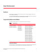
About This Document Audience This document is designed for system administrators with a working knowledge of Layer 2 and Layer 3 switching and routing. If you are using a Brocade device, you should be familiar with the following protocols if applicable to your network – IP, RIP, OSPF, BGP, ISIS, IGMP, PIM, MPLS, and VRRP.
Document conventions This section describes text formatting conventions and important notice formats used in this document.
Notice to the reader This document may contain references to the trademarks of the following corporations. These trademarks are the properties of their respective companies and corporations. These references are made for informational purposes only.
x Brocade NetIron CES 2000 Series and NetIron CER 2000 Series Hardware Installation Guide 53-1003029-02
Chapter Product Overview 1 Introduction Network planners today have to expand and extend the range of services offered further into the edge of the network. This requires extending the intelligence and high-touch processing capabilities to the network edge— whether in a metro network, a campus network or in a data center. The challenge at the edge of the network is compounded by the need to flexibly define and easily manage customer services in an intuitive manner. Further, of many rollouts.
1 Introduction • Brocade NetIron CES 2000 Series 2048F — accommodates 48-port 100/1000 Hybrid Fiber (HF) model • Brocade NetIron CES 2000 Series 2048FX — accommodates 48-port 100/1000 Hybrid Fiber (HF) model with 2x10G XFP uplink ports 2 FIGURE 1 Brocade NetIron CES 2000 Series 2024C-4X FIGURE 2 Brocade NetIron CES 2000 Series 2024F-4X FIGURE 3 Brocade NetIron CES 2000 Series 2024C FIGURE 4 Brocade NetIron CES 2000 Series 2024F Brocade NetIron CES 2000 Series and NetIron CER 2000 Series Hardwar
Introduction FIGURE 5 Brocade NetIron CES 2000 Series 2048C FIGURE 6 Brocade NetIron CES 2000 Series 2048F FIGURE 7 Brocade NetIron CES 2000 Series 2048CX FIGURE 8 Brocade NetIron CES 2000 Series 2048FX 1 There are also fourteen models in the NetIron Carrier Ethernet Router (CER and CER-RT) 2000 Series: Brocade NetIron CES 2000 Series and NetIron CER 2000 Series Hardware Installation Guide 53-1003029-02 3
1 Introduction • NetIron CER 2000 Series 2024C-4X -RT — accommodates 24-port 10/100/1000 RJ45 model with 4 combination 100/1000 Hybrid Fiber (HF) ports and 4x10G SFP+ uplinks. This device has the ability to simultaneously store up to 1.5 million IPv4 routes and up to 256,000 IPv6 routes • NetIron CER 2000 Series 2024F-4X-RT — accommodates 24-port 100/1000 Hybrid Fiber (HF) model with 4 combination 10/100/1000 RJ45 ports and 4x10G SFP+ uplinks. This device has the ability to simultaneously store up to 1.
Introduction 1 • NetIron CER 2000 Series- RT 2048FX — accommodates 48-port 100/1000 Hybrid Fiber (HF) model with 2x10G XFP uplink ports. This device has the ability to simultaneously store up to 1.
1 6 Introduction FIGURE 12 NetIron CER 2000 Series 2024F FIGURE 13 NetIron CER 2000 Series 2048C FIGURE 14 NetIron CER 2000 Series 2048F FIGURE 15 NetIron CER 2000 Series 2048CX Brocade NetIron CES 2000 Series and NetIron CER 2000 Series Hardware Installation Guide 53-1003029-02
Product overview FIGURE 16 1 NetIron CER 2000 Series 2048FX Product overview The Brocade NetIron CES 2000 Series 2000 Series is a compact 1 RU, multi-service edge or aggregation switch with a powerful set of capabilities that combine performance with rich functionality at the network edge.
1 Software features Software features Software features differ depending on the software package that is purchased with the device. The BASE package on the Brocade NetIron CES 2000 Series 2000 devices support full Layer 2 Switching and base Layer 3 (RIP and static routes). The Metro Edge Premium (ME_PREM) package support full Layer 2 Switching, base Layer 3 (RIP and static routes), Provider Bridges (IEEE 802.1ad), Provider Backbone Bridges (IEEE 802.
Hardware features 1 Hardware features This section describes the physical characteristics of the Brocade NetIron CES 2000 Series 2000 and NetIron CER 2000 Series 2000 Series devices. For details about physical dimensions, power supply specifications, and pinouts, refer to the “Hardware specifications” on page 59. The following figures show the front panels of the various NetIron 2024 and 2048 devices. NOTE This is only a representative sample.
1 Hardware features 1 10 GbE SFP+ ports 2 Four combination 10/100/1000 MbE RJ45 ports 3 Twenty-four 100/1000 MbE SFP ports Brocade NetIron CES 2000 Series 2024C The Brocade NetIron CES 2000 Series 2024C switch has twenty-four 10/100/1000 MbE RJ45 ports plus four combination 100/ 1000 MbE SFP ports, one module slot for an optional field upgradable 2-port 10 GbE XFP module, one DB9 serial management interface port labeled Console, one 10/100/1000 MbE RJ45 out-of-band management port, one resilient six
Hardware features 1 Brocade NetIron CES 2000 Series 2048C Brocade NetIron CES 2000 Series 2048C (Copper) switch has forty-eight 10/100/1000 MbE RJ45 ports plus four combination 100/ 1000 MbE SFP ports, one DB9 serial management interface port labeled Console, one 10/100/1000 MbE RJ45 out-of-band management port, one resilient six-unit fan tray, and two AC power supply bays for 1+1 redundancy with one 500W AC power supply included.
1 Hardware features Brocade NetIron CES 2000 Series 2048F Brocade NetIron CES 2000 Series 2048F (Fiber) has forty-eight 100/1000 MbE SFP ports, one DB9 serial management interface port labeled Console, one 10/100/1000 MbE RJ45 out-of-band management port, one resilient six-unit fan tray, and two AC power supply bays for 1+1 redundancy with one 500W AC power supply included.
Hardware features 1 The NetIron CER 2000 Series-RT 2024C router has more memory to support 1.5M routes, twenty-four 10/100/1000 MbE RJ45 ports plus four combination 100/ 1000 MbE SFP ports, one module slot for an optional field upgradable 2-port 10 GbE XFP module, one DB9 serial management interface port labeled Console, one 10/100/1000 MbE RJ45 out-of-band management port, one resilient six-unit fan tray, and two AC power supply bays for 1+1 redundancy with one 500W AC power supply included.
1 Hardware features NetIron CER 2000 Series 2048C NetIron CER 2000 Series 2048C (Copper) router has forty-eight 10/100/1000 MbE RJ45 ports plus four combination 100/ 1000 MbE SFP ports, one DB9 serial management interface port labeled Console, one 10/100/1000 MbE RJ45 out-of-band management port, one resilient six-unit fan tray, and two AC power supply bays for 1+1 redundancy with one 500W AC power supply included. NetIron CER 2000 Series-RT 2048C (Copper) router has more memory to support 1.
Hardware features 1 NetIron CER 2000 Series 2048F NetIron CER 2000 Series 2048F (Fiber) has forty-eight 100/1000 MbE SFP ports, one DB9 serial management interface port labeled Console, one 10/100/1000 MbE RJ45 out-of-band management port, one resilient six-unit fan tray, and two AC power supply bays for 1+1 redundancy with one 500W AC power supply included. NetIron CER 2000 Series-RT 2048F (Fiber) has more memory to support 1.
1 Hardware features Control features The front panel on each device has a combination of the following control features: • • • • • Serial Management Interface (the port labeled Console) 10/100/1000 ports with RJ-45 copper connectors 100/1000 Hybrid Fiber (HF) ports 100/1000 ports with mini-GBIC slots for SFP MSA-compliant fiber transceivers Each device that optionally has up to two 10-Gigabit Ethernet uplink ports, supports 10-Gigabit Small Form Factor Pluggable (XFP) MSA-compliant optical transceivers
Hardware features TABLE 4 LED 1 LEDs for 10-Gbps Ethernet ports Port State Meaning 10-Gbps Port LEDs on devices with two 10-Gbps ports Top Bottom Left hand port Right hand port On The port is connected. Off No fiber port connection exists. Blinking Traffic is being transmitted and received on the fiber port On The port is connected. Off No fiber port connection exists.
1 Hardware features 10-Gbps ports The Brocade NetIron CES 2000 Series 2048C-4X, Brocade NetIron CES 2000 Series 2048F-4X, NetIron CER 2000 Series 2048C-4X-RT, and the NetIron CER 2000 Series 2048F-4X-RT come with four 10-Gigabit Ethernet ports installed.
Hardware features TABLE 5 1 SFP-compliant transceivers for the 100/1000 Ethernet interface module (Continued) Part number Description E1MG-100FX 100Base-FX SFP optic multi-mode fiber, LC connector E1MG-100BXU 100Base-BXU SFP optic single-mode fiber, 1310nm, LC connector. This optic can only be connected to an E1MG-100BXD. E1MG-100BXD 100Base-BXD SFP optic single-mode fiber, 1490nm, LC connector. This optic can only be connected to an E1MG-100BXU.
1 Hardware features • • • • • Ports 1/1 – 1/24 Port 2/1 (optional 10-GbE uplink port) Port 2/2 (optional 10-GbE uplink port) Port 2/3 (optional 10-GbE uplink port) Port 2/4 (optional 10-GbE uplink port) Brocade NetIron CES 2000 Series 2048 and NetIron CER 2000 Series 2048 devices with 48 ports: • Ports 1/1 –1/24 • Ports 1/25 – 1/48 • Port 2/1 (10-GbE uplink port on Brocade NetIron CES 2000 Series 2048CX, Brocade NetIron CES 2000 Series 2048FX, NetIron CER 2000 Series 2048CX, and NetIron CER 2000 Series
Hardware features Part# : FTLX8511D3-F1 , Serial#: Port 2/2: Type : 10GBASE-SR/SW (XFP) Vendor: FOUNDRY NETWORKS, Version: Part# : TRF2000EN-LF251 , Serial#: All show media done 1 KCP02X8 02 T07J23170 Syntax: show media Power supplies Each device comes with one alternating-current (AC) or one direct-current (DC) power supply. All models have two power supply slots, enabling you to install a second power supply for redundancy.
1 Hardware features DC power supplies Figure 34 shows the DC power supply. FIGURE 34 DC Power Supply About redundant power supplies and power supply failure A device with redundant power supplies can maintain full operation when one power supply fails. Power supply failure can be a failure of the supply itself or the power grid connected to the power supply. Cooling system and fans This section describes the fans in the devices with 6 fans. Figure 35 shows the cooling fans.
Hardware features 1 The fans in the devices include six four-speed fans that operate at low speed, medium speed, medium-high speed, and high speed based on the ambient temperature and configured or default temperature thresholds. All fans operate simultaneously at the same speed. If a single fan fails within the assembly, the fan tray should be replaced. The fan tray is hot swappable and the mean time to recover (MTTR) is one minute.
1 24 Hardware features Brocade NetIron CES 2000 Series and NetIron CER 2000 Series Hardware Installation Guide 53-1003029-02
Chapter Connecting to a Network Device 2 Password assignment DANGER The procedures in this manual are for qualified service personnel. By default, the device’s CLI is not protected by passwords. To secure CLI access, Brocade strongly recommends assigning passwords. (For additional information on security, refer to Foundry Security Guide.) The CLI contains the following access levels: • Privileged EXEC – This level is also called the Enable level and can be secured by a password.
2 IP address configuration Brocade# configure terminal Brocade(config)# 3. Enter the following command to set the super-user password. Brocade(config)# enable super-user-password NOTE You must set the super-user password before you can set other types of passwords. 4. Enter the following commands to set the port configuration and read-only passwords.
IP address configuration 2 The following sub-net masks are supported by the devices: • To enter a classical network mask, enter the mask in IP address format. For example, enter “209.157.22.99 255.255.255.0” for an IP address with a Class-C sub-net mask. • To enter a prefix number for a network mask, enter a forward slash (/) and the number of bits in the mask immediately after the IP address. For example, enter “209.157.22.
2 IP address configuration Assigning an IP address to an interface, virtual interface, or loopback As you have done with other devices, you must assign an IP address to each interface and virtual interface over which user packets are routed. You can also assign an IP address to a loopback interface, which is generally used for testing and diagnostic purposes. You must use the serial connection to assign the first IP address. For subsequent addresses, you also can use the CLI through Telnet.
IP address configuration 2 Enabling and disabling the interfaces By default, all interfaces are disabled. To enable an interface, you must enter the enable command at the appropriate interface configuration level of the CLI. For example, to enable the management interface, enter the enable command at the management interface configuration level of the CLI.
2 Management port function overview NOTE The device may throw a warning that the startup-config cannot be found. This warning can be ignored. Once the device has finished reloading, it will be reset to "factory" settings. 4. Configure the device. Management port function overview You must be aware of how the system’s management port functions as described in the following: • The management port allows you to configure, monitor, and manage the system only.
Chapter 3 Installation System unpacking DANGER The procedures in this manual are for qualified service personnel. The Brocade systems ship with all of the following items. Please review the list below and verify the contents. If any items are missing, please contact the place of purchase.
3 Summary of installation tasks Summary of installation tasks Follow the steps listed below to install your Brocade device. Details for each of the steps highlighted below are provided in this chapter and in the following chapter. TABLE 8 32 Summary of installation tasks Task number Task Where to find more information 1 Ensure that the physical environment that will host the device has the proper cabling and ventilation.
Installation precautions 3 Installation precautions Follow these precautions when installing the unit. DANGER Risk of explosion if battery is replaced by an incorrect type. Replace the battery only with the same or equivalent type recommended by the manufacturer. Lithium battery is a long life battery and it is very possible that you will never need to replace it. However, should you need to replace it, do not dispose of the battery along with household waste.
3 Installation precautions Power precautions CAUTION Use a separate branch circuit for each AC power cord, which provides redundancy in case one of the circuits fails. CAUTION Ensure that the device does not overload the power circuits, wiring, and over-current protection. To determine the possibility of overloading the supply circuits, add the ampere (amp) ratings of all devices installed on the same circuit as the device. Compare this total with the rating limit for the circuit.
Installation precautions 3 CAUTION The power supply is designed exclusively for use with the Brocade NetIron CES 2000 Series and NetIron CER 2000 Series devices. The power supply produces extensive power. Installing the power supply in a device other than the Brocade NetIron CES 2000 Series and NetIron CER 2000 Series 2000 series device will cause extensive damage to your equipment. DANGER Disconnect the power cord from all power sources to completely remove power from the device.
3 Installation site preparation CAUTION For the DC input circuit (DC power supply part number RPS9-DC), make sure there is a 20 amp circuit breaker, minimum 48Vdc, double pole, on the input to the power supply. The input wiring for connection to the product should be copper wire, 12 AWG, marked VW-1, and rated minimum 90 C. CAUTION For a DC system (DC power supply part number RPS9-DC), use a grounding wire of at least 6 American Wire Gauge (AWG).
Redundant power supply installation 3 Redundant power supply installation The Brocade device ships with one alternating-current (AC) power supply or direct-current (DC) power supply. All models have two power supply slots, enabling you to install a second power supply for redundancy. If desired, you can install a second supply for redundancy.
3 Redundant power supply installation Follow the procedure given below to install an AC power supply. 1. If necessary, remove the power supply locking screws located in the upper left and the bottom right of the device (illustrated below). FIGURE 36 1 Power supply installation Power supply 2 Grounding terminals 2. If the empty power supply bay has a cover plate, remove the two screws near the edges of the cover plate to unlock the plate, then remove the plate. 3.
Redundant power supply installation 3 9. Connect the plug end of the power cord into outlet. CAUTION For the NEBS compliant installation of a Brocade NetIron CES 2000 Series 2000 or NetIron CER 2000 Series 2000 Series devices with AC and DC system use a ground wire of at least #6 American Wire Gauge (AWG).
3 Redundant power supply installation FIGURE 37 The DC power supply 4. Insert the wires into the DC wiring assembly (Figure 38). 5. Use the wire tightening screws to secure the wires. 6. Insert the DC connector with wires to the power supply and tighten the two assembly screws.
Redundant power supply installation 7. 3 With one hand, hold the bar on the front panel of the power supply. With the other hand, support the underside of the power supply, and insert the power supply into the empty power supply slot. Press until the supply is completely in the slot, so that the connectors on the back of the supply are fully engaged with the pins on the power backplane (Figure 36). CAUTION Make sure you insert the power supply right-side up.
3 Device installation CAUTION For the NEBS compliant installation of a Brocade NetIron CES 2000 Series and NetIron CER 2000 Series 2000 series devices with AC and DC system use a ground wire of at least 6 American Wire Gauge (AWG). The ground wire should have an agency-approved crimped connector (provided with the chassis) attached to one end, with the other end grounded to either a common bonding network or an isolated bonding network.
Device installation FIGURE 40 3 Front rack mount position 5 Inch offset rack mount position FIGURE 41 5 Inch offset rack mount position Brocade NetIron CES 2000 Series and NetIron CER 2000 Series Hardware Installation Guide 53-1003029-02 43
3 Device installation Mid rack mount position FIGURE 42 Mid rack mount position Reverse rack mount position FIGURE 43 44 Reverse rack mount position Brocade NetIron CES 2000 Series and NetIron CER 2000 Series Hardware Installation Guide 53-1003029-02
Device installation FIGURE 44 3 Installing the Brocade device in a rack I Installation steps 1. Mount the device in the rack as illustrated in Figure 44. 2. Using a 2-hole grounding lug and a minimum #6 AWG grounding wire, ground the chassis to either a common bonding network or an isolated bonding network. 3. Proceed to “System power” on page 46.
3 System power System power After you complete the physical installation of the system, you can power on the system. Powering on the system 1. Ensure that all power supplies are fully and properly inserted and no power supply slots are uncovered. CAUTION Never leave tools inside the device. 2. Remove the power cord from the shipping package. 3. Attach the AC power cable to the AC connector on the rear panel. 4. Insert the power cable plug into a 115V/120V outlet.
Operation verification 3 Operation verification After you have installed any redundant power supplies, verify that the device is working properly by plugging it into a power source and verifying that it passes its self test. If your device has more than one power supply installed, repeat this procedure for each power supply. Verifying proper operation 1. Connect the power cord supplied with the device to the power connector on the power supply on the rear of the device. 2.
3 Operation verification TABLE 9 LEDs for power and fan status for the 2024 models (Continued) LED Position State Meaning Power Supplies DC - same indications for both DC power supplies DC Right side of front panel Off No DC power. Amber Supply has DC power, but output is not enabled. Green Supply has DC power, is enabled, and has good output. Table 10 lists the LEDs that show power status for the Brocade NetIron CES 2000 Series and NetIron CER 2000 Series 2048 models.
PC or terminal attachment 3 The software regularly polls the hardware for power status information. You can display the status information from any management session. In addition, the software automatically generates a Syslog message and SNMP trap if a status change occurs. PC or terminal attachment To assign an IP address, you must have access to the Command Line Interface (CLI).
3 50 PC or terminal attachment Brocade NetIron CES 2000 Series and NetIron CER 2000 Series Hardware Installation Guide 53-1003029-02
Chapter Device Management Applications Familiarization 4 Management application overview This chapter describes the different applications you can use to manage the devices. The Brocade devices support the same management applications as other devices.
4 CLI Functionality Online help To display a list of available commands or command options, enter “?” or press Tab. If you have not entered part of a command at the command prompt, all the commands supported at the current CLI level are listed. If you enter part of a command, then enter “?” or press Tab, the CLI lists the options you can enter at this point in the command string. If you enter an invalid command followed by ?, a message appears indicating the command was unrecognized. For example.
CLI Functionality TABLE 11 4 CLI line editing commands Ctrl-key combination Description Ctrl-A Moves to the first character on the command line. Ctrl-B Moves the cursor back one character. Ctrl-C Escapes and terminates command prompts and ongoing tasks (such as lengthy displays), and displays a fresh command prompt. Ctrl-D Deletes the character at the cursor. Ctrl-E Moves to the end of the current command line. Ctrl-F Moves the cursor forward one character.
4 CLI Functionality NOTE The vertical bar (|) is part of the command. Note that the regular expression specified as the search string is case sensitive. In the example above, a search string of “Internet” would match the line containing the IP address, but a search string of “internet” would not. Displaying lines that do not contain a specified string The following command filters the output of the show who command so it displays only lines that do not contain the word “closed”.
CLI Functionality 4 Brocade# ? append attrib boot cd chdir clear clock configure copy cp debug delete dir dm dot1x erase exit fastboot force-sync-standby Append one file to another Change file attribute Boot system from bootp/tftp server/flash image Change current working directory Change current working directory Clear table/statistics/keys Set clock Enter configuration mode Copy between flash, tftp, config/code Copy file commands Enable debugging functions (see also 'undebug') Delete file on flash List
4 CLI Functionality --More--, next page: Space, next line: Return key, quit: Control-c -telnet The filtered results are displayed. filtering...
CLI Functionality TABLE 12 4 Special characters for regular expressions (Continued) Character Operation $ A dollar sign matches on the end of an input string.
4 58 CLI Functionality Brocade NetIron CES 2000 Series and NetIron CER 2000 Series Hardware Installation Guide 53-1003029-02
Appendix 5 Hardware Specifications This chapter provides the following specifications for the Brocade devices: • “Hardware specifications” • “Port specifications” • “Power cords” Hardware specifications This section contains the following hardware specifications for the Brocade devices: • • • • • “Power specifications” “Physical dimensions” “Operating environment” “Storage environment” “Safety agency approvals” Power specifications This section contains the power specifications for the Brocade devic
5 Hardware specifications TABLE 14 Maximum power calculations at 100-240 VAC with two PSUs (Continued) Devices Watts BTUs per hour Brocade NetIron CES 2000 Series 2024F-4X with 4x10G uplink installed 268 915 Brocade NetIron CES 2000 Series 2024F 145 495 Brocade NetIron CES 2000 Series 2024F with 2x10G uplink installed 195 666 Brocade NetIron CES 2000 Series 2048C 205 700 Brocade NetIron CES 2000 Series 2048CX 255 870 Brocade NetIron CES 2000 Series 2048F 245 836 Brocade NetIron CES
Hardware specifications TABLE 15 5 Physical dimensions of the Brocade devices Devices Height Width Depth Weight (fully-loaded) (LB) Brocade NetIron CES 2000 Series 2024C 1 RU 1.7 inches 4.4 cm 17.44 in 44.3 cm 17.64 in 44.8 cm 15.5 Brocade NetIron CES 2000 Series 2024C with 2x10G uplink installed 1 RU 1.7 inches 4.4 cm 17.44 in 44.3 cm 17.64 in 44.8 cm 17.5 Brocade NetIron CES 2000 Series 2024F-4X 1 RU 1.7 inches 4.4 cm 17.44 in 44.3 cm 17.30 in 43.9 cm 21.
5 Hardware specifications TABLE 15 Physical dimensions of the Brocade devices Devices Height Width Depth Weight (fully-loaded) (LB) NetIron CER 2000 Series 2024F-4X-RT with 4x10G uplink installed 1 RU 1.7 inches 4.4 cm 17.44 in 44.3 cm 17.30 in 43.9 cm 21.8 NetIron CER 2000 Series 2024F 1 RU 1.7 inches 4.4 cm 17.44 in 44.3 cm 17.64 in 44.8 cm 15.5 NetIron CER 2000 Series 2024F with 2x10G uplink installed 1 RU 1.7 inches 4.4 cm 17.44 in 44.3 cm 17.64 in 44.8 cm 17.
Port specifications 5 • Total air flow: 267 LFM • Fan operating noise: • Based on ISO 7779 • < 60 dB-A Safety agency approvals • CAN/CSA-22.2 No.
5 Port specifications ports as described in GR-1089-CORE, Issue 4) and require isolation from the exposed OSP cabling. The addition of Primary Protectors is not sufficient protection in order to connect these interfaces metallically to OSP wiring. Console port pin assignments The console port is a standard male DB-9 connector, as shown in Figure 45.
Power cords FIGURE 46 5 Console port pin assignments showing cable connection options to a terminal or PC Management port pin assignments The management port is an RJ-45 UTP connector. Table 18 describes the connector’s pin assignments.
5 Power cords TABLE 19 Power cord types (international) Country Plug style NEMA 5-15P 125V only USA, Canada, Japan, other locations CEE-7/7 “Schuko” Continental Europe BS-1363A various locations AS 3112 Australia/New Zealand Argentina X Australia X Austria X Bahrain X Belgium X Brazil X Canade X Chile X China, People’s Rep. X Czech, Rep.
5 Power cords TABLE 19 Power cord types (international) (Continued) Country Plug style NEMA 5-15P 125V only USA, Canada, Japan, other locations Malaysia Mexico CEE-7/7 “Schuko” Continental Europe BS-1363A various locations Alternate IEC-60309 16A, 3 wire, 220-250V Recommended X Monaco X Netherlands X New Zealand X Norway X Poland X Portugal X Puerto Rico AS 3112 Australia/New Zealand X Russia X Saudi Arabia X Scotland X Singapore X South Africa X Spain X Sweden X Sw
5 Power cords NOTE NEMA 5-15P should only be considered after taking into account the total power consumption on the system. Before you choose NEMA 5-15P on the system, calculate the total power consumption on the system to see whether NEMA 5-15P can support the power draw as per the country's legal requirements or contact Brocade technical support.
Chapter Hardware Maintenance 6 Hardware maintenance schedule DANGER The procedures in this manual are for qualified service personnel. The Brocade device requires minimal maintenance for its hardware components. Brocade recommends cleaning the fiber-optic connectors on a fiber-optic port and the connected fiber cable each time you disconnect the cable.
6 Power supply replacement Installation precautions and warnings Follow these precautions when installing a power supply in the Brocade device. DANGER Before beginning the installation, refer to the precautions in “Power precautions” on page 34. CAUTION Do not install the device in an environment where the operating ambient temperature might exceed 40o C (104o F). CAUTION Never leave tools inside the chassis.
Power supply replacement 6 This command displays status information for the power supplies and the fans. The power supplies are numbered from left to right. These numbers assume you are facing the front of the device, not the rear. If the display indicates “Installed (Failed)” for any of the slots, the power supply installed in that particular slot has failed.
6 Power supply replacement Removing the AC power supply Required tools You will need the following tool to perform this procedure: • #2 Phillips-head screwdriver The following procedures are required when removing an AC power supplies from a device. 1. Unplug the power supply from the power source. 2. Disconnect the power cord from the power supply. 3. Unscrew the two power supply locking screws located at the top left and bottom right hand corner of the power supply.
Power supply replacement FIGURE 49 6 Removing the power supply from the device 5. Continue to pull the power supply until it is removed from the device. 6. Place the power supply in an anti-static bag for storage. 7. Insert a new supply, or place and screw in a cover plate over the empty power supply. Refer to “Installing the AC power supply” on page 73 for details. Installing the AC power supply Perform the following steps to install an AC power supply. 1.
6 Power supply replacement FIGURE 50 Power supply installation CAUTION Make sure you insert the power supply right-side up. It is possible to insert the supply upside down, although the supply will not engage with the power backplane when upside down. The power supply is right-side up when the manufacturer label is on the top. 4. Tighten the two power supply locking screws located at the top left and bottom right hand corner of the power supply. 5. Connect the power cord to the power supply.
Power supply replacement FIGURE 51 1 6 DC power supply screws Chassis attachment screws 2 Assembly screws 4. Unscrew the chassis attachment screws to unlock the power supply itself (Figure 51).
6 Power supply replacement 5. Pull the power supply outward once the screws have been unscrewed. This will disconnect the power supply from the backplane. Pull it completely free of the chassis. 6. Place the power supply in an anti-static bag for storage. 7. Insert a new supply, or place and screw in a cover plate over the empty power supply. Refer to “Installing a DC power supply” on page 76 for details.
Power supply replacement FIGURE 54 6 The DC wiring assembly 1 Wire tightening screws 2 Assembly screws 7. With one hand, hold the bar on the front panel of the power supply. With the other hand, support the underside of the power supply, and insert the power supply into the empty power supply slot. Press until the supply is completely in the slot, so that the connectors on the back of the supply are fully engaged with the pins on the power backplane (Figure 50).
6 Power supply replacement FIGURE 55 1 DC power supply screws Chassis attachment screws 2 Assembly screws 9. Connect the wire to your DC power source, making sure to connect the -48V cable to the negative terminal on the power supply and the 0V cable to the positive terminal as marked on the power supply. The equipment installation must meet NEC/CEC code requirements. Consult local authorities for regulations.
Power supply replacement 6 CAUTION To insure adequate bonding when attaching the provided Panduit LCD6-10AF two-hole ground lug, a minimum of 20 PSI of torque is required to be applied to the mounting hardware used to attach the ground lug. Use a star washer to ensure an NEBS compliant connection. Verifying proper operation To verify the proper operation of the power supply after power on, you can observe the LEDs on the power supply.
6 10-Gigabit Ethernet module installation or replacement The LEDs for Fan, PS1 and PS2 are located on the right side of the front panel for Brocade NetIron CES 2000 Series and NetIron CER 2000 Series 2024 models (On the Brocade NetIron CES 2000 Series 2048 and NetIron CER 2000 Series 2048 models, these LEDs are located on the left side of the front panel). The software regularly polls the hardware for power status information. You can display the status information from any management session.
Replacing the fan tray 6 CAUTION For safety reasons, the ESD wrist strap should contain a series 1 Meg ohm resistor Removing a 2 x10-Gigabit Ethernet module Follow the procedure given below while removing a 2 x10-Gigabit Ethernet module. 1. Power off the Brocade device. 2. Use a #2 Phillips-head screwdriver to loosen the screws on the 2 x10-Gigabit module. 3. Remove the 2 x10-Gigabit module. 4. Place the 2 x10-Gigabit module in an anti-static bag for storage. 5.
6 Copper or Fiber optic module replacement To replace the Brocade fan tray, follow these steps. 1. Power down and unplug the chassis. 2. Unscrew the two screws that secure the fan tray to the chassis. FIGURE 56 Replacing the fan tray 3. Slide the fan tray out 4. Slide the new fan tray in and tighten the screws to secure it to the chassis. 5. Plug the chassis back in and power up.
Copper or Fiber optic module replacement 6 CAUTION For safety reasons, the ESD wrist strap should contain a series 1 Meg ohm resistor. • The protective covering that you removed from the copper or fiber optic module when you initially installed the module. Follow the steps given below to remove a copper or fiber optic module from a Gigabit Ethernet or 10-Gigabit Ethernet port. 1. Put on the ESD wrist strap and ground yourself by attaching the clip end to a metal surface (such as an equipment rack). 2.
6 Copper or Fiber optic module replacement Before installing one of these modules into the port, obtain an ESD wrist strap with a plug for connection to a metal surface. CAUTION All fiber-optic interfaces use Class 1 Lasers. CAUTION For safety reasons, the ESD wrist strap should contain a series 1 Meg ohm resistor. Perform the following tasks to install a fiber optic module. 1.
Fiber optic connector cleaning 6 Tunable 10 GbE DWDM SFP+ NOTE Tunable 10 GbE DWDM SFP+ are only supported on NetIron CES and NetIron CER 4x10G models only. The tunable 10 GbE dense wavelength-division multiplexing (DWDM) SFP+ modular optic (part number 10G-SFPP-ZRD-T) can be configured through the CLI to use C-band channels 1 - 102 for flexible metro or campus Ethernet links that reach up to 80 km. For 10-Gigabit Ethernet DWDM interfaces only, configure full C-band tunable optics as shown below.
6 86 Fiber optic connector cleaning Brocade NetIron CES 2000 Series and NetIron CER 2000 Series Hardware Installation Guide 53-1003029-02
Appendix Regulatory Statements A U.S.A. This equipment has been tested and found to comply with the limits for a Class A digital device pursuant to Part 15 of the FCC Rules. These limits are designed to provide reasonable protection against harmful interference when the equipment is operated in a commercial environment.
A Japan Japan The following statements apply to the Brocade devices. English translation of above statement This is Class A product based on the standard of the Voluntary Control Council For Interference by Information Technology Equipment (VCCI). If this equipment is used in a domestic environment, radio disturbance may arise. When such trouble occurs, the user may be required to take corrective actions.
Taiwan A Taiwan English translation of above statement Warning: This is Class A product. In a domestic environment this product may cause radio interference in which case the user may be required to take adequate measures.
A China China 90 Brocade NetIron CES 2000 Series and NetIron CER 2000 Series Hardware Installation Guide 53-1003029-02
Appendix Caution and Danger Notices B The caution and danger notices that appear in this manual are listed below in English, German, French, and Spanish. Cautions A caution calls your attention to a possible hazard that can damage equipment. “Vorsicht” weist auf die Gefahr einer möglichen Beschädigung des Gerätes in. Une mise en garde attire votre attention sur un risque possible d'endommagement de l'équipement. Ci-dessous, vous trouverez les mises en garde utilisées dans ce manuel.
B 92 Cautions CAUTION Make sure the air flow around the front, sides, and back of the device is not restricted. VORSICHT Stellen Sie sicher, dass an der Vorderseite, den Seiten und an der Rückseite der Luftstrom nicht behindert wird. MISE EN GARDE Vérifiez que rien ne restreint la circulation d'air devant, derrière et sur les côtés du dispositif et qu'elle peut se faire librement.
Cautions B CAUTION Make sure you insert the power supply right-side up. It is possible to insert the supply upside down, although the supply will not engage with the power backplane when upside down. The power supply is right-side up when the power connector is on the left and the fan vent is on the right. VORSICHT Sicher Sie sicher, dass Sie das Netzteil mit der richtigen Seite nach oben weisend einstecken. Man kann die Karte auch umgekehrt einstecken.
B 94 Cautions CAUTION Use the erase startup-config command only for new systems. If you enter this command on a system you have already configured, the command erases the configuration. If you accidentally do erase the configuration on a configured system, enter the write memory command to save the running configuration to the startup-config file. VORSICHT Verwenden Sie den Befehl "Erase startup-config" (Löschen Startup-Konfig) nur für neue Systeme.
Cautions B CAUTION Changes or modifications made to this device that are not expressly approved by the party responsible for compliance could void the user's authority to operate the equipment. VORSICHT Falls dieses Gerät verändert oder modifiziert wird, ohne die ausdrückliche Genehmigung der für die Einhaltung der Anforderungen verantwortlichen Partei einzuholen, kann dem Benutzer der weitere Betrieb des Gerätes untersagt werden.
B Danger CAUTION For a DC system (DC power supply part number RPS9-DC), use a grounding wire of at least 6 American Wire Gauge (AWG). The 6 AWG wire should be attached to an agency-approved crimp connector, crimped with the proper tool. VORSICHT Für Geräte mit Gleichstromversorgung (Gleichstromnetzteil, Teilenummer RPS9-DC) muss zur Erdung ein Kabel der Stärke 6 AWG (American Wire Gauge) verwendet werden.
Danger B WARNING Make sure the rack or cabinet housing the device is adequately secured to prevent it from becoming unstable or falling over. GEFAHR Stellen Sie sicher, dass das Gestell oder der Schrank für die Unterbringung des Geräts auf angemessene Weise gesichert ist, so dass das Gestell oder der Schrank nicht wackeln oder umfallen kann. DANGER Vérifiez que le bâti ou le support abritant le dispositif est bien fixé afin qu'il ne devienne pas instable ou qu'il ne risque pas de tomber.
B 98 Danger WARNING If the installation requires a different power cord than the one supplied with the device, make sure you use a power cord displaying the mark of the safety agency that defines the regulations for power cords in your country. The mark is your assurance that the power cord can be used safely with the device.
Danger B WARNING Before beginning the installation, refer to the precautions in“Power precautions” on page 34. GEFAHR Vor der Installation siehe Vorsichtsmaßnahmen unter “Power precautions” (Vorsichtsmaßnahmen in Bezug auf elektrische Ablagen) auf den Seiten 34. DANGER Avant de commencer l'installation, consultez les précautions décrites dans “Power precautions” (Précautions quant à l'alimentation), pages 34.
B 100 Danger Brocade NetIron CES 2000 Series and NetIron CER 2000 Series Hardware Installation Guide 53-1003029-02