
User Manual v12.3.0 User Manual

Brocade Network Advisor SAN User Manual 1151
53-1003154-01
Flow Monitor
29
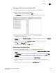
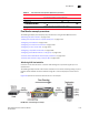
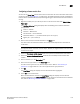
FIGURE 503 Flow Vision dialog box (Monitor Flows table)
Table 94 describes information on sub-flows displayed in the Flows table when you select
Monitor from the Feature list above the Flows table.
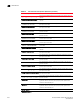
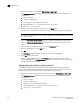
TABLE 94 Flows table fields and components (Monitor flow)
Fields and components Description
Violation MAPS violation for the flow over the time duration selected. This col-
umn gets updated dynamically for every 5 mins with the violation
count receiving from MAPS.
Sub Flow ID The sub-flow database identifier.
Target Switch The switch on which you created the flow definition.
Frame Type All frame types defined in the flow definition.
Flow Name The user-defined name for the flow definition.
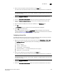
Source The source identifiers defined in the flow definition.
Source Info The icon and name for the source device. The device name is a hyper
link. Click to launch the device’s property sheet.
This field is empty if the source device is not defined in the flow
definition.
Destination The port number of the destination device defined in the flow
definition. An * (asterisk) indicates learned flows.
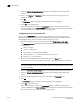
Destination Info The icon and name for the destination device. The device name is a
hyper link. Click to launch the device’s property sheet.
This field is empty if the destination device is not defined in the flow
definition.
Port Status The operational status (online or offline) for the port.