
User Manual v12.3.0 User Manual

Brocade Network Advisor SAN User Manual 1173
53-1003154-01
Flow Monitor
29
When the flow definition activates, the Flow Vision dialog box displays with the new flow
selected (highlighted) in the Flow Definitions table. To review the sub-flow data for the selected
flow, refer to “Monitoring a Flow Monitor flow” on page 1149".
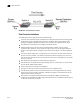
Configuring a backbone-to-edge flow through an egress port using fabric IDs
The following example creates a flow (b2e_src_dcx_fid) that filters frames passing from a
backbone fabric (128) to the edge fabric (100) using a specific ingress port (219).
1. Right-click the EX_Port (219) on which you want to monitor the flow and select Fabric Vision >
Flow > Add.
The Add Flow Definition dialog box displays with the following default criteria and flow
identifiers pre-populated:
• Feature — Monitor
• Direction — Bidirectional
• Source Device — Source identifier
• Destination Device — * (an asterisk allows you to use any port)
• Egress port — port number (219)
2. Enter a name (b2e_src_dcx_fid) for the flow definition in the Name field.
The name cannot be over 20 characters and can only include alphanumeric characters or
underscores.
NOTE
For a physical switch, the name must be unique. However, for logical switches, the name does
not have to be unique.
3. Select the Source to Destination option for Direction.
4. Select the Persist over switch reboots check box to persist this flow definition over reboots.
5. Select the Activate all selected features check box to immediately activate the flow after
creation.
6. Select the Port Address option for End Device.
7. Enter the source port ID (01f001) in the Source field.
8. Enter an asterisk (*) for the destination port ID in the Destination field.
9. Select the Fabric ID option for FCR/XISL mode.
10. Enter the backbone fabric ID (100) in the Source field.
To select the source from a list, refer to “Selecting a fabric or virtual fabric ID from a list of
available products” on page 1147".
11. Enter the edge fabric ID (128) in the Destination field.
To select the destination from a list, refer to “Selecting a fabric or virtual fabric ID from a list of
available products” on page 1147".
12. Select OK to save the definition.
When the flow definition activates, the Flow Vision dialog box displays with the new flow
selected (highlighted) in the Flow Definitions table. To review the sub-flow data for the selected
flow, refer to “Monitoring a Flow Monitor flow” on page 1149".