
Configuration Guide Manual

Brocade TurboIron 24X Series Configuration Guide 217
53-1003053-01
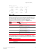
Digital optical monitoring
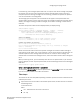
TurboIron> show optic 4
Port Temperature Tx Power Rx Power Tx Bias Current
+----+-----------+----------+------------+-------------------+
1 30.8242 C -001.8822 dBm -002.5908 dBm 41.790 mA
Normal Normal Normal Normal
2 31.7070 C -001.4116 dBm -006.4092 dBm 41.976 mA
Normal Normal Normal Normal
3 30.1835 C -000.5794 dBm 0.000 mA
Normal Low-Alarm Normal Low-Alarm
4 0.0000 C 0.000 mA
Normal Normal Normal Normal
Syntax: show optic <slot number>
NOTE
This function takes advantage of information stored and supplied by the manufacturer of the XFP or
SFP transceiver. This information is an optional feature of the Multi-Source Agreement standard
defining the optical interface. Not all component suppliers have implemented this feature set. In
such cases where the XFP or SFP transceiver does not supply the information, a “Not Available”
message will be displayed for the specific port on which the module is installed.
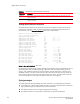
The following table describes the information displayed by the show optic command.
For Temperature, Tx Power, Rx Power, and Tx Bias Current in the show optic command output,
values are displayed along with one of the following alarm status values: Low-Alarm, Low-Warn,
Normal, High-Warn or High-Alarm. The thresholds that determine these status values are set by the
manufacturer of the optical transceivers. Table 45 describes each of these status values.
TABLE 44 Output from the show optic command
This field... Displays...
Port The TurboIron X Series port number.
Temperature
• The operating temperature, in degrees Celsius, of the optical
transceiver.
• The alarm status, as described in Table 45.
Tx Power
• The transmit power signal, in decibels (dB), of the measured power
referenced to one milliwatt (mW).
• The alarm status, as described in Table 45.
Rx Power
• The receive power signal, in decibels (dB), of the measured power
referenced to one milliwatt (mW).
• The alarm status, as described in Table 45
Tx Bias Current
• The transmit bias power signal, in milliamperes (mA).
• The alarm status, as described in Table 45.
TABLE 45 Alarm status value description
Status value Description
Low-Alarm Monitored level has dropped below the "low-alarm" threshold set by the manufacturer of the
optical transceiver.
Low-Warn Monitored level has dropped below the "low-warn" threshold set by the manufacturer of the
optical transceiver.
Normal Monitored level is within the "normal" range set by the manufacturer of the optical transceiver.