
Hardware Installation Guide User Manual

52 Brocade TurboIron 24X Series Hardware Installation Guide
53-1002981-01
Device specifications
A
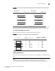
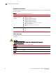
Mean time between failure
Table 11 lists the Mean Time between Failure (MTBF) for the TurboIron 24X. The MTBF is the
average estimated time, in hours, before a hardware failure may occur.
Pinouts and signalling
This section lists the pinouts for the DB-9 connector and RJ-45 port jacks.
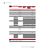
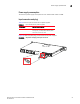
Serial (Console) port pinouts
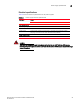
The Console port is a standard male DB-9 connector, as shown in Figure 26.
FIGURE 26 Serial port pin and signalling details
Most PC serial ports also require a cable with a female DB-9 connector. Terminal connections will
vary, requiring either a DB-9 or DB-25 connector, male or female.
Serial cable options between the TurboIron 24X and a PC or terminal are shown in Figure 27.
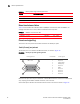
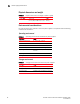
TABLE 10 Device power surge and drop protection
Property Protection Mechanism
Power surge MOV and Spark Gap protection
Power drop The PSU will shut down after AC loss >20ms
Maximum power draw 300 watts
TABLE 11 MTBF for the TurboIron 24X
Configuration or Module Temperature MTBF (hours)
TurboIron 24X (40°C) 104°F 114,572
Pin Assignment
DB-9 mal
Pin Number
Switch Signal
6
1 Reserved
2 TXD (output)
3 RXD (input)
4 Reserved
5 GND
6 Reserved
7 Reserved
8 Reserved
9 Reserved
1 5
9
e