53-1002944-01 Rev.B 22 July 2013 ® Universal Four Post Rack Kit Installation Procedure Supporting Brocade VDX 6740T 53-1002944-01 Rev.
Copyright © 2013 Brocade Communications Systems, Inc. All Rights Reserved. ADX, AnyIO, Brocade, Brocade Assurance, the B-wing symbol, DCX, Fabric OS, ICX, MLX, MyBrocade, OpenScript, VCS, VDX, and Vyatta are registered trademarks, and HyperEdge, The Effortless Network, and The On-Demand Data Center are trademarks of Brocade Communications Systems, Inc., in the United States and/or in other countries. Other brands, products, or service names mentioned may be trademarks of their respective owners.
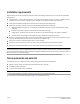
Contents This document provides instructions to install a 1U, 1.5U, or 2U switch (or SAN Router) in a 19-in. (48.3 cm) EIA rack using the Universal Four Post Rack Kit. The document is organized as follows: • Introduction. . . . . . . . . . . . . . . . . . . . . . . . . . . . . . . . . . . . . . . . . . . . . . . . . . . . • Installation requirements. . . . . . . . . . . . . . . . . . . . . . . . . . . . . . . . . . . . . . . . . • Tool requirements and parts list . . . . . . . . . . . . . . . . . . . . . .
Installation requirements Allow 15 to 30 minutes to complete this procedure. Note the following requirements to ensure correct installation and operation: • Provide space in a 19-in. (48.3 cm) EIA rack, as required for the switch type, with a minimum distance of 24 in. (609.60 mm) and a maximum distance of 32 in. (812.80 mm) between the front and back posts. • Verify that the additional weight of the switch does not exceed the rack weight limits.
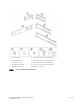
1 Front brackets (2) 6 Screw, 8-32 x 5/16-in., panhead Phillips (8) 2 Bracket extensions (2) 7 Screw, 8-32 x 5/16-in., flathead Phillips (16) 3 Rear bracket, short (2) 8 Screw, 6-32 x 1/4-in., panhead Phillips (8) 4 Rear bracket, medium (2) 9 Screw, 10-32 x 5/8-in., panhead Phillips (8) 5 Rear bracket, long (2) 10 Retainer nut, 10-32 (8) FIGURE 1 Items in the Universal Four Post Rack Kit Universal Four-Post Rack Kit Installation Procedure 53-1002944-01 Rev.
Installation procedure for flush-front mounting ATTENTION The switch must be turned off and disconnected from the fabric during this procedure. NOTE Although this document describes how to install single-height (1U) and double-height (2U) switches, the illustrations show a single-height switch as a typical installation.
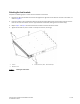
Attaching the front brackets Complete the following steps to attach the front brackets to the switch. 1. Position the right front bracket with the flat side against the right side of the switch at the front of the switch, as shown in Figure 2. 2. Insert four 8-32 x 5/16-in. flathead screws through the vertically aligned holes in the bracket and then into the holes on the side of the switch. Use the upper and lower screw holes, leaving the center holes empty. 3.
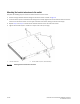
Attaching the bracket extensions to the switch Complete the following steps to attach the bracket extensions to the switch. 1. Position the right bracket extension along the side of the switch as shown in Figure 3. 2. Insert four 8-32 x 5/16-in. flathead screws through the vertically aligned holes in the extension and then into the holes on the side of the switch. Use the upper and lower screw holes, leaving the center holes empty. 3.
Installing the switch in the rack Complete the following steps to install the switch in the rack. 1. Position the switch in the rack, as shown in Figure 4, providing temporary support under the switch until the rail kit is secured to the rack. 2. Attach the right front bracket to the right front rack post using two 10-32 x 5/8-in. panhead screws and two retainer nuts. Use the upper and lower holes in the bracket. 3. Attach the left front bracket to the left front rack post using two 10-32 x 5/8-in.
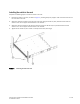
Attaching the rear brackets to the extensions Complete the following steps to attach the rear brackets to the extensions. There are short, medium and long rear brackets you can use for this step. Choose the correct bracket for the depth of your rack. 1. Select the proper length rear bracket for your rack depth. 2. Slide the right rear bracket onto the right extension, as shown in Figure 5. The short rear brackets are shown. Use the first and third vertical pairs of holes for the screws.
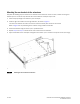
1 Bracket, rear, medium or long FIGURE 6 2 Screws, 6-32 x 1/4-in., panhead Phillips Attaching the medium or long rear brackets to the extensions Universal Four-Post Rack Kit Installation Procedure 53-1002944-01 Rev.
Attaching the rear brackets to the rack posts Complete the following steps to attach the rear brackets to the rack posts. 1. Attach the right rear bracket to the right rear rack post using two 10-32 x 5/8-in. panhead screws and two retainer nuts, as shown in Figure 7. Use the upper and lower holes in the bracket. 2. Attach the left rear bracket to the left rear rack post using two 10-32 x 5/8-in. panhead screws and two retainer nuts. Use the upper and lower holes in the bracket. 3.
Installation procedure for flush-rear (recessed) mounting This approach is similar to the flush-front mounting except that the brackets are reversed on the switch. ATTENTION The switch must be turned off and disconnected from the fabric during this procedure.
Attaching the front brackets to the rear of the switch NOTE In this installation, the brackets are named as called out in the parts list even though the installation of the brackets is reversed from the flush front installation. Complete the following steps to attach the front brackets to the rear of the switch. 1. Position the right front bracket with the flat side against the right rear side of the switch, as shown in Figure 8. 2. Insert four 8-32 x 5/16-in.
Attaching the extensions to the front of the switch Complete the following steps to attach the extensions to the front of the switch. 1. Position the right extension along the side of the switch as shown in Figure 9. 2. Attach the bracket using four 8-32 x 5/16-in. flathead screws. 3. Repeat step 1 and step 2 to attach the left front extension to the left side of the switch. 4. Tighten all the 8-32 x 5/16-in. screws to a torque of 15 in-lbs (17 cm-kgs).
Installing the switch in the rack Complete the following steps to install the switch in the rack. 1. Position the switch in the rack, as shown in Figure 10, providing temporary support under the switch until the rail kit is secured to the rack. 2. Attach the right front bracket to the right rear rack post using two 10-32 x 5/8-in. panhead screws and two retainer nuts. Use the upper and lower holes in the bracket. 3. Attach the left front bracket to the left rear rack post using two 10-32 x 5/8-in.
Attaching the rear brackets to the extensions at the front of the switch Complete the following steps to attach the rear brackets to the extensions. There are short, medium and long front brackets you can use for this step. Choose the correct bracket for the depth of your rack. 1. Select the proper length rear bracket for your rack depth. 2. Slide the right rear bracket onto the right extension, as shown in Figure 11. The short rear brackets are shown.
1 Bracket, rear, medium or long FIGURE 12 18 of 20 2 Screws, 6-32 x 1/4-in., panhead Phillips Attaching the medium or long rear brackets to the extensions Universal Four-Post Rack Kit Installation Procedure 53-1002944-01 Rev.
Attaching the rear brackets to the front rack posts Complete the following steps to attach the rear brackets to the front rack posts. 1. Attach the right rear bracket to the right front rack post using two 10-32 x 5/8-in. screws and two retainer nuts, as shown in Figure 13. Use the upper and lower holes in the bracket. 2. Attach the left rear bracket to the left front rack post using two 10-32 x 5/8-in. screws and two retainer nuts. Use the upper and lower holes in the bracket. 3.
of 20 Universal Four-Post Rack Kit Installation Procedure 53-1002944-01 Rev.