53-1002943-01 22 July 2013 ® Universal Two-Post Rack Kit Installation Procedure Supporting the Brocade VDX 6740T 53-1002943-01 *53-1002943-01*
Copyright © 2013 Brocade Communications Systems, Inc. All Rights Reserved. ADX, AnyIO, Brocade, Brocade Assurance, the B-wing symbol, DCX, Fabric OS, ICX, MLX, MyBrocade, OpenScript, VCS, VDX, and Vyatta are registered trademarks, and HyperEdge, The Effortless Network, and The On-Demand Data Center are trademarks of Brocade Communications Systems, Inc., in the United States and/or in other countries. Other brands, products, or service names mentioned may be trademarks of their respective owners.
Contents This document provides instructions to install a Brocade VDX 6740T (1U) switch in a two-post telecommunications (Telco) rack using the Universal Two-Post Rack Kit. The document is organized as follows. • Introduction. . . . . . . . . . . . . . . . . . . . . . . . . . . . . . . . . . . . . . . . . . . . . . . . . . . . • Installation requirements. . . . . . . . . . . . . . . . . . . . . . . . . . . . . . . . . . . . . . . . . • Tool requirements and parts list . . . . . . . . . . . . . . . . . . .
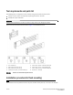
Tool requirements and parts list The following items are required to install a switch using the universal two-post rack kit: • Clamps or other means of temporarily supporting the switch in the rack. • Phillips #2 torque screwdriver ATTENTION Use the screws specified for use with the switch. Longer screws can damage the switch. Ensure that the items listed and illustrated in Figure 1 are included in the kit.
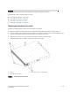
ATTENTION The switch must be turned off and disconnected from the fabric during this procedure. Complete these tasks to install the switch in a rack: • • • • “Attaching front brackets to the switch” “Attaching front brackets to the rack” “Attaching rear brackets to the rack” “Attaching rear brackets to the switch” Attaching front brackets to the switch Complete the following steps to attach the front brackets to the switch. 1.
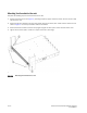
Attaching front brackets to the rack Complete the following steps to install the switch in the rack. 1. Position the switch in the rack (Figure 3), providing temporary support under the switch until the rack kit is fully secured to the rack. 2. Attach the right front bracket to the right rack upright using two 10-32 x 5/8-in. screws and two retainer nuts as shown in Figure 3. Use the top and bottom holes in the bracket. 3. Attach the left front bracket to the left rack upright using two 10-32 x 5/8-in.
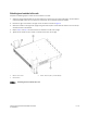
Attaching rear brackets to the rack Complete the following steps to attach the rear brackets to the rack. 1. Select the proper length bracket for your post width. If your posts are three to five inches wide, use the brackets marked 3-5 INCH. If your posts are five to six inches wide, use the brackets marked 5-6 INCH. 2. Position the right rear bracket in the right rear of the switch as shown in Figure 4. 3. Attach the brackets to the right rack upright using two 10-32 x 5/8-in. screws and two retainer nuts.
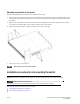
Attaching rear brackets to the switch Complete the following steps to attach the rear brackets to the switch. 1. Align the right rear bracket to the right rear of the switch and using four 8-32 x 5/16-in. panhead screws, attach the bracket to the switch as shown in Figure 5. Be sure to insert the screws through the upper and lower slots in the bracket. 2. Align the left rear bracket to the left rear of the switch and using four 8-32 x 5/16-in. panhead screws, attach the bracket to the switch.
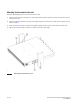
• “Attaching rear brackets to the rack” • “Attaching rear brackets to the switch” Attaching front brackets to the switch Complete the following steps to attach the front brackets to the switch. 1. Position the right front bracket with the flat side against the right side of the switch as shown in Figure 6. 2. Insert four 8-32 x 5/16-in. flathead screws through the top and bottom holes of the vertically aligned series of holes in the bracket and then into the pair of holes on the side of the switch. 3.
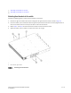
Attaching front brackets to the rack Complete the following steps to install the switch in the rack. 1. Position the switch in the rack (Figure 7), providing temporary support under the switch until the rail kit is fully secured to the rack. 2. Attach the right front bracket to the right rack upright using two 10-32 x 5/8-in. screws and two retainer nuts as shown in Figure 7. 3. Attach the left front bracket to the left rack upright using two 10-32 x 5/8-in. screws and two retainer nuts. 4.
Attaching rear brackets to the rack Complete the following steps to attach the rear brackets to the rack. 1. Select the proper length bracket for your post width. If your posts are three to five inches wide, use the brackets marked 3-5 INCH. If your posts are five to six inches wide, use the brackets marked 5-6 INCH. 2. Position the right rear bracket in the right rear of the switch as shown in Figure 8.
Attaching rear brackets to the switch Complete the following steps to attach the rear brackets to the switch. 1. Align the right rear bracket to the right rear of the switch and using four 8-32 x 5/16-in. panhead screws, attach the bracket to the switch as shown in Figure 9. Be sure to insert the screws through the upper and lower slots in the bracket. 2. Align the left rear bracket to the left rear of the switch and using four 8-32 x 5/16-in. panhead screws, attach the bracket to the switch.