53-1002555-01 22 August 2012 ® Brocade VDX 8770-8 QuickStart Guide 53-1002555-01 *53-1002555-01*
Copyright © 2012, Brocade Communications Systems, Incorporated. Brocade, Brocade Assurance, the B-wing symbol, BigIron, DCX, Fabric OS, FastIron, MLX, NetIron, SAN Health, ServerIron, TurboIron, VCS, and VDX are registered trademarks, and AnyIO, Brocade One, CloudPlex, Effortless Networking, ICX, NET Health, OpenScript, and The Effortless Network are trademarks of Brocade Communications Systems, Inc., in the United States and/or in other countries.
In this guide • Introduction. . . . . . . . . . . . . . . . . . . . . . . . . . . . . . . . . . . . . . . . . . . . . . . . . . . . • Safety notices . . . . . . . . . . . . . . . . . . . . . . . . . . . . . . . . . . . . . . . . . . . . . . . . . . • Danger notices . . . . . . . . . . . . . . . . . . . . . . . . . . . . . . . . . . . . . . . . . . . . . . . . . • Caution notices. . . . . . . . . . . . . . . . . . . . . . . . . . . . . . . . . . . . . . . . . . . . . . . . . • ESD precautions . . . . . . . .
Introduction You can set up and install the Brocade VDX 8770-8 in the following ways: • As a standalone unit on a flat surface • In a four-post rack • In a two-post telecommunications (Telco) rack This manual describes how to set up the Brocade VDX 8770-8 as a standalone unit. For rack mount installation instructions, refer to the manual that comes with the separately ordered rack kit.
TABLE 1 Installation tasks, time, and items required (Continued) Installation task Time estimate Items required Installing transceivers as needed 30-60 minutes Copper and optical transceivers and direct-attach cables as needed. Attaching cables, cable ties, and cable guides 2-3 hours Cables, cable ties, and cable comb. CAUTION The Brocade VDX 8770-8 with DC power sources are intended for installation in restricted access areas only.
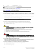
Caution notices A caution notice calls attention to a situation that is potentially hazardous to people because of some existing condition. Read and comply with the following caution notice before installing or servicing this device. CAUTION Use safe lifting practices when moving the product. (C015) ESD precautions The Brocade VDX 8770-8 contains ESD-sensitive FRUs. When working with any Brocade VDX 8770-8 FRU, use correct electrostatic discharge (ESD) procedures.
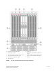
1 Line cards L1 through L4 (left to right) 6 Intake Vent 2 Cable management comb 7 Management modules MM1 and MM2 (left to right) 3 Switch fabric modules S1 through S6 (odd numbers above, even numbers below, left to right) 8 Power supplies 1 through 8 (1 through 4 above, left to right, 5 through 8 below, left to right)) 4 Line cards L5 through L8 (left to right) 9 ESD jack 5 Mounting flanges FIGURE 1 Port side of the Brocade VDX 8770-8 (sample configuration) Brocade VDX 8770-8 QuickStart
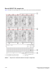
Brocade VDX 8770-8, nonport side Figure 2 displays a sample configuration of the nonport side view of the Brocade VDX 8770-8.
Items included with the Brocade VDX 8770-8 The Brocade VDX 8770-8 ships with the following items: • Brocade VDX 8770-8 chassis, populated with: (management modules, switch fabric modules, and line cards are all packaged separately) - Management modules (one) Switch fabric modules (up to six) Line cards (up to eight) Filler panels for unoccupied slots for all modules Power supplies (up to eight) Power supply filler panels for unoccupied bays Fan assemblies (four) • Accessory kit containing the following
Preparing for the Brocade VDX 8770-8 installation NOTE Refer to the safety notices before installation (“Safety notices”). Refer to “Power specifications” to plan for meeting power supply standards before installing the chassis. Refer to “Environmental requirements” to plan for your environmental needs. Refer to “Managing cables” to plan for cable management. The following steps are required to ensure correct installation and operation. 1. Provide a space that is 15 rack units (15U) high, 61.29 cm (24.
• Either access to an FTP server or a Brocade USB device for backing up the switch configuration or collecting supportsave output data (optional) • Transceivers (copper and optical) and compatible cables and direct-attach cables if needed 5. Ensure that the air intake and exhaust vents have a minimum of 5.1 cm (2 in.) of airspace. 6. Ensure that the air temperature on the air intake side is less than 40°C (104°F) during operation.
You can calculate your power requirements by combining the power demands for the various modules and fan units in your configuration. While you may use fewer ports in a given line card, it is always safer to use the power requirement of a fully populated card.
TABLE 4 Environmental requirements (Continued) Condition Acceptable range during operation Acceptable range during non-operation Shock 20G, 6 ms duration, half-sine wave 33G, 11 ms duration, half-sine wave Vibration 0.5G p-p, 5-500 Hz at 1.0 octave/minute 2.0G p-p, 5-500 Hz at 1.0 octave/minute Airflow Maximum: 1250 cu ft/min. (2124 cu m/hr) Nominal: 325 cu ft/min.
NOTE The Brocade VDX 8770-8 packaging incorporates a wood pallet and brackets. The switch sits on top of a corrugated cardboard shipping tray. c. Save the packing materials for use when returning a switch. d. Leave the switch on top of the shipping tray and pallet if the switch must be transported to the installation location. 2. Use a pallet jack or other assisted lift to transport the new switch to the installation area. 3.
• 12x40G line card module — Ports are numbered from 1 through 12 from from top to bottom when installed in the switch. Refer to Figure 3.
• 48x1G and 48x10G line card modules — Ports are numbered from 1 through 48, from top to bottom, with the odd-numbered ports on the right row and the even-numbered ports on the left row when installed in the switch. Refer to Figure 4. FIGURE 4 48x10G line card (48x1G line card similar) Inserting a management module For this procedure, refer to “ESD precautions” and Figure 5. Complete the following steps to insert an MM. 1. Unpack the new MM and remove it from the anti-static bag. 2.
5. Align the module pan with the guides in the slot. The first MM should be installed in slot M1. 6. Slide the MM into the slot until it is firmly seated. 7. Rotate the ejectors away from the center of the module face until the module is tight in the slot. 8. Tighten the captive screws using the Phillips screwdriver. FIGURE 5 Inserting a management module Inserting a switch fabric module For this procedure, refer to “ESD precautions” and Figure 6. Complete the following steps to insert the SFM. 1.
5. Open the ejectors on the new SFM by rotating them toward the center of the module face. Orient the switch fabric module so that the ejectors are toward you. 6. Align the module pan with the guides in the slot. The first SFM ashould be installed in slot S3. 7. Push the SFM firmly into the slot. 8. Close the ejectors by rotating them away from the center of the SFM. The levering action of the ejectors seats the module in the slot. 9. Tighten the captive screws using the Phillips screwdriver. 10.
Complete this procedure to insert a new line card. 1. Unpack the new line card and remove it from the anti-static bag. 2. Inspect the module for damage. 3. Remove the protective covers from the backplane connectors. 4. Orient the line card so that the ports are at the front of the switch. 5. Open the ejectors by rotating them toward the center of the line card face and align the flat side of the line card inside the top and bottom rail guides in the slot.
Inserting power supplies The chassis can be powered with either AC or DC power supplies. They are slightly different in appearance and in the way that the power cord is attached. Follow the procedure below for your type of power supply. Refer to Figure 8. FIGURE 8 Inserting a power supply Inserting an AC power supply For this procedure, refer to “ESD precautions” and Figure 8. To replace a power supply, complete the following steps. DANGER High Touch Current.
4. Insert the power supply into the slot. 5. Rotate the handle upward to fully seat the power supply. 6. Tighten the captive screw. Inserting a DC power supply For this procedure, refer to “ESD precautions” and Figure 8. To replace a DC power supply, complete the following steps. 1. Unpack the new power supply and remove it from the anti-static bag. 2. Inspect the power supply for damage. 3. Use a #1 Phillips screwdriver to remove the screw that secures the safety cover over the power lugs.
3. Crimp the #2 AWG power supply wires into the power lugs. 4. Connect the power lugs to the power supply unit. Connect the -48V wire to the negative terminal and the 0V wire to the positive terminal. NOTE The DC return must be isolated from the chassis ground (DC-I) when making connections to the connections to the power supply. 5. Replace the safety cover. 6. Plug the other end of the cable into the power source. ATTENTION Do not connect the switch to the network until the IP addresses are configured.
• The fabric is aware of all members, devices, and Virtual Machines (VMs). Automatic Migration of Port Profiles (AMPP) supports VM migration to another physical server. If the VM moves, it is automatically reconnected to all of its original resources. Establishing a serial connection to the Brocade VDX 8770-8 The serial port is located on the port side of the Brocade VDX 8770-8. The switch uses an RJ-45 connector for the serial port. An RJ-45 to DB9 adapter is also provided with the Brocade VDX 8770-8.
tip /dev/ttya -9600 Serial cable pinouts Table 6 lists the serial cable pinouts. TABLE 6 Serial cable pinouts PIN Signal Description 1 Not supported NA 2 Not supported NA 3 TXD Transmit data 4 GND Logic ground 5 Not supported NA 6 RXD Receive data 7 Not supported NA 8 Not supported NA Logging in to the serial console port Log in to the Brocade VDX 8770-8 through the serial connection with the admin user name. The default password is password.
The reply to command will include a line about the setting of the RBridge ID. Successfully set rbridge-id. Assigning permanent passwords The factory-configured default accounts on the switch are admin and user. Use the default administrative account as shown in Table 7 to log in to the switch for the first time and to perform the basic configuration tasks. The user account is read-only and used primarily for system monitoring.
1. Log in to the MM using the default password (the default password is password). 2. Enter configuration mode using the configure terminal command. 3. Specify the chassis with the rbridge-id command. switch(config)# rbridge-id 1 4. Use the chassis virtual-ip command to set the IP address for the chassis. switch(config-rbridge-id 1)# chassis virtual-ip 10.20.236.132/20 5. Use the ip address command to set the Ethernet IP address for the MMs.
By establishing an Ethernet connection, you can complete the Brocade VDX 8770-8 configuration using a serial session, Telnet, or management application, such as Brocade Network Advisor. NOTE To protect the Ethernet port from damage, keep the cover on the port when not in use. Perform the following steps to establish an Ethernet connection to the Brocade VDX 8770-8. 1. Remove the shipping plug from the Ethernet port on the active MM. 2. Insert one end of an Ethernet cable into the Ethernet port. 3.
switch(config)# switch-attributes 1 chassis-name B8770_prime 2. Record the new name for reference. 3. To verify the new chassis name you can run the show running-config switch-attributes [rbridge-id] command. switch# show running-config switch-attributes 1 Setting the date and time The MM maintains the current date and time inside a battery-backed real-time clock (RTC) circuit. Date and time are used for logging events.
Synchronizing local time using NTP Perform the following steps to synchronize the local time using NTP. 1. Log in to the switch using the default password (the default password is password). 2. Enter configure terminal to change to global configuration mode. switch# configure terminal Entering configuration mode terminal 3. Enter the ntp server "IPv4 address" command, where IPv4 address is the IP address of the first NTP server in IPv4 format, which the switch must be able to access.
1. If necessary, log in to the switch using the default password (the default password is password). Be sure you are in privileged EXEC mode. 2. Enter the clock set year-month-dayT hours:minutes:seconds command. The following example sets the clock to March 17, 2012, 15 minutes past noon. switch# clock set 2012-03-17T12:15:00 If you want to show the clock and time zone settings, use the show clock [rbridge-id rbridge-id | all] command.
The current running configuration, containing all of your latest changes, is saved to the startup configuration. The next time the switch reboots, all of the changes will remain in force. Verifying correct operation Complete the following steps to verify correct operation for the Brocade VDX 8770-8. 1. Check the LEDs to verify that all components are functional. 2. If necessary, log in to the switch by Telnet, using the admin account. 3.
Connecting network devices You can connect your chassis to a variety of network devices. Refer to the topics below for some specific requirements for making these conections. Connecting to Ethernet devices For copper connections to a 10/100Base-TX or 1000Base-T switch or another Brocade device, a crossover cable is required. NOTE The 802.3ab standard (automatic MDI or MDIX detection) calls for automatic negotiation of the connection between two 1000Base-T ports.
1. Add the transceivers and cables to the line card ports. Position one of the optical transceivers so that the key is oriented correctly to the port. Insert the transceiver into the port until it is firmly seated and the latching mechanism clicks. Transceivers are keyed so that they can only be inserted with the correct orientation. If a transceiver does not slide in easily, ensure that it is correctly oriented. 2.
Following is a list of recommendations: • Leave at least 1 m (3.28 ft) of slack for each port cable. This provides room to remove and replace the Brocade VDX 8770-8, allows for inadvertent movement of the rack, and helps prevent the cables from being bent to less than the minimum bend radius. • The minimum bend radius should be no smaller than ten times the cable radius. The minimum radius to which a 50 micron cable can be bent under full tensile load is 5.1 cm (2 in.).