
Administrators Guide (Supporting Fabric OS v7.3.0) Manual


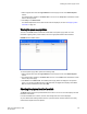
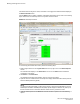
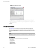

FIGURE 32 Switch Status Policy dialog box
3. Configure the numerical and percentage values to conform to your definition of a healthy switch.
For the selected row, the corresponding field description is displayed in the panel underneath.
4. Optional: Right-click a row in the table to access options to copy the values to your clipboard, or to
export the values to a file.
5. Click OK.
Port LED interpretation
The Switch View on page 41 displays port graphics with blinking LEDs, simulating the physical
appearance of the ports. One of the LEDs indicates port status; the other indicates port speed. For
LED information, refer to the hardware documentation for the switch you are viewing. (The blink rate of
the LEDs in the Switch View does not necessarily match the blink rate of the LEDs on the physical
switch.)
NOTE
All 8 Gbps and 16 Gbps Brocade switches and port blades do not have port speed LEDs, but only port
status LEDs.
Port icon colors
The background color of the port icon indicates the port status, as follows:
• Green (healthy)
• Yellow (marginal)
• Red (critical)
• Gray (unmonitored)
• Blue (buffer-limited)
• Dimmed (unlicensed)
Port LED interpretation
166 Web Tools Administrator's Guide
53-1003169-01