AUTOMATIC FOOD SERVICE EQUIPMENT AUTOMATIC GAS BROILER MODEL 9025 (CCSI CONTROL) OWNERS MANUAL IMPORTANT: RETAIN THIS MANUAL IN A SAFE PLACE FOR FUTURE REFERENCE. FOR YOUR SAFETY: Do not store or use gasoline or other flammable vapors or liquids in the vicinity of this or any other appliance. WARNING: Improper installation, adjustment, alteration, maintenance can cause property damage, injury, or death.
TABLE OF CONTENTS A. General Information . . . . . . . . . . . . A.1 Description . . . . . . . . . . . . . . A.2 Warranty Information . . . . . . A.3 Service/Technical Assistance A.4 Safety Information . . . . . . . . . . . . . . . . . . . . . . . . . . . . . . . . . . . . . . . . . . . . . . . . . . . . . . . . . . . . . . . . . . . . . . . . . . . . . . . . . . . . . . . . . . . . . . . . . . . . . . . . . . . . . . . . . . . . . . . . . . . . . . . . . . . . . . . . . . . . . .
A. GENERAL INFORMATION A.1 Description The Nieco® Model 9025 automatic broiler, utilizes dual broil chambers, high release convection burners, electric elements, a new, simplified ignition system, easy cleaning and a state-of-the-art computer control to help eliminate broiling problems and provide the operator with even greater control over the broiling environment.
A.3 Service/Technical Assistance If you experience any problems with the installation or operation of your broiler, contact your local Authorized Nieco Distributor. Fill in the information bellow and have it handy when calling your authorized service agency for assistance. The serial number is on the broiler rating plate on the side of the unit. Purchased from: Date of Purchase: Model No.: Serial No.: For the name of your local Authorized Nieco Distributor, please call (800) 821-2141.
A.4 Important Safety Information (Cont.) In addition to the warnings and cautions in this manual, use the following guidelines for safe operation of your Nieco Automatic Broiler: • • • • • Read and follow all instructions before using this equipment. Install or locate broiler only for its intended use as described in this manual. Do not operate this equipment if it has a damaged cord or plug, if it is not working properly or if it has been otherwise damaged.
B. INSTALLATION B.1 Pre-Installation Uncrate the broiler and inspect for shipping damage. Remove the tape securing the machine parts, and install the parts in their proper location. Refer to the Parts and Location section of this manual. If there are obvious or concealed damages to any part of the broiler, please contact your freight carrier. The factory warranty does not cover freight damage. B.2 Mounting Follow the mounting instructions if this function is not performed by the installer. B.
B.4 Hood Requirements This appliance must be installed under a ventilation hood of adequate size and the following minimum capacity: Model 9025 SCFM 1000 Do not obstruct the flow of combustion and ventilation air. An adequate air supply must be available for safe and proper operation. B.5 Clearance For proper installation the minimum clearance from combustible and non-combustible construction must be 305 mm (12”) from the back and 305 mm (12”) from the front of the machine.
B.6 Gas Connection- 1” N.P.T. (Nieco P/N 11966; 1” Flexible Gas Line) At rated input the gas supply should deliver a minimum pressure of at least 15 mbar (5" water column) at the broiler connection for natural gas. Incoming gas supply pressure must not exceed 50 mbar (14" water column). Note: The installation of this appliance must conform with local codes, or in the absence of local codes, with the National Fuel Gas Code, ANSI Z223.1, Natural Gas Installation Code, CAN/CGA-B149.1 including: 1.
B.8 Restraining Device Installation and Use This high strength restrainer is to be used with all moveable (castered) appliances. It fully complies with American Gas Association requirements. References: Z21.69, Z83.11, and Z21.41 with current revisions. Installation is quick and positive. In Canada, device is in accordance with CAN 1-6.9-M70 Quick Disconnect Devices for use with gas fuel, and CAN 1-6.10-88 metal connectors for gas appliances.
C. OPERATION C.
C.1 Controls and Indicators (Cont.) (1) (2) READY RESET (3) (4) (5) (6) (7) ENTER SELECT BELT SELECTION (8) (9) L LEFT 1 (12) 4 2 CHICKEN (13) SPECIAL 2 (15) 5 R RIGHT THICK BURGER SPECIAL 1 (14) (10) CENTER WHOPPER (11) C 3 SPECIAL 3 (16) 6 (1) READY - Green indicator light when temperature set point is reached. (9) CENTER - Center (FLEX) Broil Belt information will be displayed on LCD screen if pushed. (2) RESET - Clears broil chain error and silences warning alarm.
C.2 Lighting Procedures PRE-LIGHTING PREPARATION 1. Broiler is centered under hood and plugged in 2. Gas valve is open when handle is in line (parallel to) the pipe 3. Turn ventilation system on WARNING THE VENTILATION SYSTEM MUST BE ON AT ALL TIMES DURING BROILER OPERATION. OPERATING BROILER WITHOUT PROPER VENTILATION IS A SEVERE FIRE HAZARD. MAIN CHAMBER IGNITION c 1 2 Turn the MAIN POWER SWITCH (a) on.
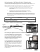
C.2 Lighting Procedures (Cont.) MANUAL IGNITION - MAIN CHAMBER 1 Press and hold the LOWER PILOT BUTTON (a). Use match or long-stemmed lighter to light PILOT TUBES (b). Light the pilot closest to the feed end of the broiler. After pilot has lit, hold pilot button for 30 seconds, release and verify that lower burners have lit. Repeat for the UPPER PILOT BUTTON (c). c b a LIGHTER/MATCH 2 After releasing red pilot buttons; check GAS PRESSURE GAUGE (a) reading. Gauge should read 4”.
C.3 Shutdown Procedures PLANNED SHUTDOWN 1. Allow the broiler to run free of any product for 10 minutes. This will burn the chain clean. 2. Turn off the Main Power Switch (a). 3. Wait for 30 minutes for the broiler to cool. a WARNING CAUTION Always leave the ventilation hood on while the broiler is cooling. Failure to do so is both a fire risk and could result in damage to the broiler. Allow the broiler to fully cool BEFORE beginning disassembly and cleaning.
C.4 Control Operation IMPORTANT: THIS BROILER IS SHIPPED WITH FACTORY PRESETS THAT MUST BE CHANGED. If this is the initial start-up for your broiler, ALL control settings must be made according to BURGER KING® specifications. Follow the steps outlined for calibration, changing preset times and setting the flex chamber element heat settings to properly set up this broiler. INITIAL SET-UP AND CALIBRATION 1 2 Turn Main Power Switch on.
NORMAL RUN (OPERATING) SCREENS The readout display actually has 8 lines, however only 4 are visible at a time. The first visible set shows cook times for the upper broil chains. The second set shows the return belt time and the time and date stamp. To switch between the sets press the SELECT button. 1 RUN SCREEN 1 Normal Run Screen Press the SELECT (a) or ENTER (b) button until the screen returns to the normal run screen.The normal run screen shows cook times and broiler temperatures.
CHANGING PRESET COOK TIMES The 9025 control allows you to program multiple belt speeds for each individual belt. Follow these steps to change the preset broil times for each product/belt. 1 From the normal operating screen - press and hold for 5 seconds the BELT you wish to change. For example press LEFT (a). Belt selection choices are: LEFT (Main Chamber), CENTER and RIGHT (both Flex Chamber).
CHANGING FLEX CHAMBER ELEMENT POWER SETTINGS The flex chamber on the 9025 uses electric elements on the top and gas burners on the bottom. The elements are divided into 2 cook zones per belt. These are defined as HEATER 1 (Htr 1) and HEATER 2 (Htr 2). Heater 1 is the front or feed end elements; Heater 2 is the back or discharge end elements.These zones can be independently controlled. The heaters are set by percent of power ranging from 0% (OFF), to 100% (full power).
SETTING THE DATE AND TIME 1 MAIN FLEX Press and hold SELECT (a) for 5 seconds to get to the TEMP SET screen. Press the SELECT (b) button to move the cursor to point at SETUP, then press the ENTER (c) button. EXIT ENTER SELECT PARAMETERS FEEDER DROP SPEED CALIBRATION EXIT Press the SELECT (a) button to move the arrow to the CLOCK selection. Press the ENTER (b) button. a c TEST CLOCK ENTER b C O SET CLOCK/CALENDAR MON DA/YR HR.MN.SC xxx xx/xx xx.xx.
D. CLEANING AND DISASSEMBLY Turn broiler off and close the main gas valve. Disconnect the power supply to the broiler before cleaning or servicing. If this broiler is connected using a restraint, and disconnection of the restraint is necessary for cleaning or moving the broiler, the restraint must be reconnected after the broiler has been returned to its originally installed position. Allow to cool for 30 minutes prior to cleaning/disassembly. Leave the ventilation system on during cooling.
Loader Cover - P/N 11386 Disassemble Feed End Clean 2 a. Wash b. Scrub c. Rinse d. Sanitize Slide towards yourself Slide on; the fit is very tight y4 Ever s r Hou Reassemble Loader Base - P/N 11211 Disassemble 28 Feed End Clean 3 a. Wash b. Scrub c. Rinse d.
Loader Housing - P/N 11389 Disassemble Feed End Clean 4 a. Wash b. Scrub c. Rinse d. Sanitize Lift and pull Hang housing on the brackets Reassemble Flex Slide - P/N 11755 Disassemble 26 Feed End Clean 5 a. Wash b. Scrub c. Rinse d.
Front Hood Shield (NOT A NIECO PART) Disassemble Feed End Clean 6 Wipe down front and back surface Lift, pull off Lift up into exhaust hood; set down to lock in place If hinged shield Release rod from hood frame Close hood shield Lock lever If hinged shield; swing shield up Reassemble Secure in place with rod to hood frame Main Chamber Ash Scraper Tray P/N 11014 Disassemble 24 Feed End Clean 7 a. Wash b. Scrub c. Rinse d.
Upper Grease Pans (2) - MAIN P/N 10737/FLEX P/N 10452 Disassemble Feed End Clean 8 a. Wash b. Degrease c. Scrub d. Rinse e. Sanitize Slide pan out Slide pan into slot Correct Incorrect Reassemble Warming Platens (2) Feed End Clean 9 a.
Feed End Grease Troughs (2) MAIN P/N 11540/FLEX P/N 11542 Disassemble Feed End Clean 10 a. Wash b. Degrease c. Scrub d. Rinse e. Sanitize Lift up and out Hook in the slot Reassemble Feed End Ash Scraper Blades (2) - MAIN P/N 11016/FLEX P/N 11015 Disassemble 21 Feed End Clean 11 a. Wash b. Degrease c. Scrub d. Rinse e.
Awnings (2) - MAIN P/N 11837/FLEX P/N 11830 Disassemble Discharge End Clean 12 a. Wash b. Scrub (on inside only) c. Rinse d. Sanitize Tilt to unhook; lift pins off brackets; pull out Slide up and under frame; place pins in brackets Reassemble Side Panels (2) - P/N 10747 Disassemble 19 Sides Clean 13 a. Wipe clean b.
Return Slides (2) - MAIN P/N 11495 (CENTER DIVIDER P/N 11493)/FLEX P/N 11497 Disassemble 14 Clean a. Wash b. Degrease c. Scrub d. Rinse e. Sanitize Pull up and out Discharge End Place bracket over broiler crossbar; set down Make sure slide is on correct chamber Incorrect Position center guide on pan Reassemble Stripper Blades (2) - MAIN P/N 10857/FLEX P/N 10856 Disassemble Clean 15 a. Wash b. Degrease c. Scrub d. Rinse e.
Chain Shafts (3) Discharge End Clean 16 a.Scrape shafts Clean top chain shafts with multipurpose tool Multipurpose tool is stored behind the side panel Reassemble Return Chains (2) - MAIN P/N 11412/FLEX P/N 11555 Disassemble Pull and hold spring loaded pin Discharge End Clean 17 a. Wash b. Scrub c. Rinse d.
Lower Grease Trays (2) - MAIN P/N 11553/FLEX P/N 11551 Disassemble Discharge End Clean 18 a. Wash b. Scrub c. Rinse d. Sanitize Lift from grease trough slot; slide out Slide into place; fit bracket into slot Reassemble Grease Troughs (2) - MAIN P/N 10943/FLEX P/N 10943 Disassemble Clean 19 a. Wash b. Degrease c. Scrub d. Rinse e.
Grease Bucket - P/N 9089 Disassemble Discharge End Clean 20 a. Wash b. Degrease c. Scrub d. Rinse e. Sanitize Lift off Hang bucket by handle over hook on broiler If used with liner Remove and discard used liner; put in new liner Reassemble Discharge Ash Scrapers (2) - MAIN P/N 11006/FLEX P/N 11004 Disassemble 12 Discharge End Clean 21 a. Wash b. Degrease c. Scrub d. Rinse e.
Lower Burners (6) - P/N 10532 Disassemble Discharge End Clean 22 Brush with dry brush NO WATER Twist counterclockwise and pull thly Mon Lower Burner Shields (6) - P/N 10036 Disassemble Install burner with round end facing feed end with holes up Push and turn clockwise to make sure burner is secure and holes are facing up Reassemble 10 Discharge End Clean 23 a. Wash b. Scrub c. Rinse d.
Catalyst (if available) - NOT A NIECO PART Disassemble 24 Top Rotate kly Wee Grasp handle and lift up to remove from shroud collar Clean Lift up, rotate 1/2 turn and fit over shroud Handle should be at top thly Mon Rinse with water only; air dry Do not use chemicals on a catalyst Perforated Cap (2 if no catalyst) - P/N 11863 Disassemble CAUTION: EXTREMELY HOT Reassemble 8 Top Clean 25 a. Wash b. Scrub c. Rinse d.
Shrouds (2) - MAIN P/N 11706/FLEX P/N 11704 Disassemble Top Clean 26 a. Wash b. Scrub c. Rinse d.
Main Chamber Reverberators (4) - P/N 10151 Disassemble Top Clean 28 a. Wash b. Scrub c. Rinse Slide off; inspect for breaks/damage; replace if necessary thly Mon Slide onto upper burners Make sure reverberator is loose Replace when any breakage occurs in screen surface Reassemble Flex Chamber Element Reflectors (4) - P/N 10450 Disassemble Clean 29 a. Wash b. Scrub c.
Orifices (10) Inside Clean 30 Clean 4 upper burner orifices and 6 lower burner orifices Clean main burner orifices with Nieco brush P/N 11731 thly Mon Pilot Burners (4) Top Clean 31 Clean all pilot burners and orifices Clean slot with a utility knife blade; clean orifices with Nieco Brush P/N 11731 thly Mon 35 Nieco Corporation - Model 9025
Flame Arrestors/Chain Supports (6) Disassemble Sides MAIN P/N 10680/FLEX P/N 10683 Rotate 32 Daily Lift and open arrestor door Daily rotation is essential. If discharge arrestor #3 is plugged, it will cause burning and charring of product Pull out each arrestor and inspect for wear Rotate 3 arrestors using multipurpose tool to push arrestors F E E D 1 2 D I S C H A R G E 3 Clean a. Wash b. Scrub c.
Frame and Cross Rod Inside Clean 34 Using multipurpose tool for cross rod Cross Rod Frame Wipe down frame Grease Extractors - NOT A NIECO PART Disassemble Hood Clean 35 a. Degrease b. Scrub c.
Temperature Probe Shield - P/N 10755 Disassemble Hood Clean 36 a. Degrease b. Scrub c. Rinse Lift up and out of broiler Note position for proper reassembly. Shield hangs on cross rod. iSem ly al annu Reassemble Use a cloth with rubbing alcohol to clean the temperature probes (Main and Flex) on a monthly basis.
E. TROUBLESHOOTING Always verify that the broiler is properly assembled, the hood is on, gas valve open and broiler is plugged in.
Problem No display on computer control keypad Solution ❏ ❏ If there is no text displayed on the keypad but the backlighting is on, check the connection at the keypad Call service if necessary Alternative display shown on computer control keypad ❏ Depress select button on the keypad to change view Return chain jams ❏ ❏ Remove any obstruction if needed Press the black reset button located on the left (MAIN CHAMBER) side of the broiler control box (underneath).
Problem Meat patties not returning Solution ❏ ❏ Check that patties have not gotten stuck on the return slide __ Remove awnings to check __ Remove product from return slide if necessary __ Proper cleaning of return slide is needed daily to remove buildup which can cause patties to stick Check return chain to see if patties are stuck in chain __ Remove product, then check to make sure the broiler has been assembled properly (Awnings, return slide and stripper blades) Temperature on display reads “OPEN” ❏
F. BROIL CHAIN REMOVAL Maintain proper tension on the conveyor chains to prevent jamming. Major tension adjustments are made by removing a link or links from the chain. Broil belt tension should be checked monthly. To do this, allow the machine to cool, then grip the idler shaft at each end and pull on it. If the shaft and bearings move 1/2” or more, remove a link from the conveyor belt. Before beginning, notice the way the broil chain runs through the broiler.
Cover P/N 12122 Lane Divider (3) P/N 11387 Ash Scraper Blade P/N 11016 Nieco Corporation - Model 9025 On Broiler (not shown) Engagement Pin Black Knob Sprocket, 13T 1/2" Bore Sprocket, 13T, 5/8" Bore P/N 11194 P/N 11608 P/N 6007 P/N 6040 Enclosure P/N 11389 Bar Only P/N 11378 Push Bar Assembly P/N 11211 Feeder Drive Hub P/N 11194 Feed End Grease Trough P/N 11540 Perforated Shroud Cap P/N 11863 Reverberator (4) Lower Burner P/N 10151 Shield (3) P/N 10036 Arrestor Access Door P/N 10925 Produc
Grease Trough P/N 10943 Return Chain Assy P/N 11555 Return Chain 15" P/N 11571 Sprocket P/N 11565 Bearing P/N 11478 Discharge Ash Scraper P/N 11004 Stripper Blade P/N 10856 Return Slide P/N 11497 Awning P/N 11830 Element Reflectors (4) P/N 10450 Grease Bucket P/N 9089 Catalyst Shroud P/N 11704 Lower Grease Tray P/N 11551 Flame Arrestor (3) P/N 10683 Multi-Purpose Tool P/N 11108 Lower Burner (3) P/N 12193 Flex Product Slide P/N 11755 Ash Scraper Blade P/N 11015 Side Panel (2) P/N 10747 Ar
Red Pilot Button (2) P/N 2123 Upper Thermocouple P/N 2101 Lower Thermocouple P/N 2024 Gas Gauge P/N 2001 Keypad Overlay P/N 10176 Keypad Circuit Board P/N 10505 Return Motor Reset P/N 11737 45 Ignition Reset Switch P/N 11025 Main Power Switch P/N 10503 Gas Gauge P/N 2001 Red Pilot Button P/N 2123 Thermocouple P/N 2024 G.
18.
Combination Gas Valve P/N 2209 Switch Box Cover P/N 10815 Lower Pilot Orifice P/N 2018 Lower Burner Orifice (3) P/N 2015 Carryover Orifice P/N 2018 7.
G.
H.
I. SPECIFICATIONS AUTOMATIC B ROILER MODEL 9025 ITEM NO. AIA 11400 Model 9025 The Nieco Model 9025 is the state of the art broiling system designed for maximum versatility. The 9025 features an automatic loader, computerized control, simplified ignition, dual broil chambers, automatic product return chain and heated holding section.
AUTOMATIC B ROILER MODEL 9025 49.25 (1251) DIMENSIONS Length Height Width INCH 40.00 67.43* 49.25 MM 1016 1712 1251 Broil Chain * If your broiler is equipped with a catalyst add 1.5” to the overall height. A 2” stand extension is available for improved freezer clearance. 67.43* (1713) ENERGY 62.37 (1584) Gas connection: 1” N.P.T. 56.00 (1422) Electrical Connection (specify exact voltage): 208-240V 3Ø 50/60Hz 23A Natural Gas BTU/hr 3” W.C.
J. WARRANTY INFORMATION 1. Seller guarantees new Nieco automatic infrared equipment against defective workmanship and materials for a period of twelve months from the date of installation with the exception of the inconel radiant surfaces, protective shields, reverberators, and electric broiling elements which are guaranteed for a period of six months from date of installation. The results of ordinary wear, neglect or misuse, accident or excessive deterioration from any cause are not considered defects.
Nieco Corporation • 7950 Cameron Drive • Windsor, CA 95492 • (707) 284-7100 Office • (707) 284-7430 Fax Reorder # 9999-25 3/02 www.nieco.com • e-mail: nieco@nieco.