1Mbps W ireless LAN Module Quick Guide Rev 0.
Regulatory Compliance FCC Interference Statement This equipment has been tested and found to comply with the limits for a Class B digital device, pursuant to part 15 of the FCC Rules. These limits are designed to provide reasonable protection against harmful interference in a residential installation. This equipment generates, uses and can radiate radio frequency energy and, if not installed and used in accordance with the instructions, may cause harmful interference to radio communications.
Wireless LAN module quick guide Table of contents CHAPTER 1 Introduction Features What is Wireless LAN? LAN Modes Notes on wireless LAN configuration CHAPTER 2 Hardware installation Hardware description Status LEDs CHAPTER 3 Using the Wireless Utility Installation & description APPENDIX A Troubleshooting Q&A APPENDIX B Specifications ii
Cha pt e r 1 Introduction Thank you for using the Wireless LAN module. This high-speed Wireless LAN module provides you with an innovative wireless networking solution. The module is easy to set up and use.
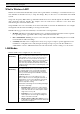
Wireless LAN module quick guide What is Wireless LAN? Wireless Local Area Network (WLAN) systems offer a great number of advantages over traditional wired systems. WLANs are flexible and easy to setup and manage. They are also more economical than wired LAN systems. Using radio frequency (RF) technology, WLANs transmit and receive data through the air. WLANs combine data connectivity with user mobility.
—Introduction Notes on wireless LAN configuration When configuring a wireless LAN (WLAN), be sure to note the following points: • Optimize the performance of the WLAN by ensuring that the distance between access points is not too far. In most buildings, WLAN cards operate within a range of 100 ~ 300 feet, depending on the thickness and structure of the walls. • Radio waves can pass through walls and glass but not metal.
Cha pt e r 2 Hardware installation This chapter covers how to installing the wireless LAN module in your embedded system. Hardware description The Wireless LAN Module has a 50-pin connector for attaching to the 50-pin port of embedded system. And please refer to the following table for these 50-pin definition.
—Hardware installation And also please refer to the following for the module’s dimension.
Wireless LAN module quick guide Status LEDs The following table describes the meaning of the LEDs of the module. LED 6 MEANING PWR Indicates that the Card is powered on. LINK Indicates link status. It is normally blinking. When blinking, indicates that the card is scanning the channels, and the link is not active. When lit, indicates that the card is locked to a channel, and the link is active.
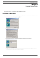
—Using the Wireless Utility Cha pt e r 3 Using the Wireless Utility The following sections cover the Wireless utility installation and usage. Installation & description After you have installed the wireless LAN module on the system, you can install wireless utility on the client side to check wireless status. Please follow the steps below. 1. Run SETUP.EXE, the following screen appears: 2. Click Next. The following screen appears: 3. Read the End User License Agreement and click Yes.
Wireless LAN module quick guide 5. Choose the Network Mode for your wireless node. 6. Click Next. The following screen appears: 7. Select the default path for the wireless utility or browse to an alternate path. Then click Next. The following screen appears: 8. Type in a Program Folder name or select the default name and click Next. Setup installs the software and the following screen appears: 9. Click Finish to finish the utility installation.
—Using the Wireless Utility After you have installed the utility, you will see the wireless utility icon in the Windows taskbar: FreePort utility icon Double-click the icon to open the wireless utility.
Wireless LAN module quick guide The following table describes the wireless utility: State: displays the connection status. Current Channel: displays the channel. Current Tx Rate: displays the wireless bandwidth in megabits per second. Throughput: displays the transfer and receive rates in bytes per second. Link Quality: when connected to the wired LAN, displays the connection integrity. Signal Strength: when connected to the wired LAN, displays the signal strength.
—Using the Wireless Utility disable power saving mode. Channel: enables you to select a transmission channel. The Encryption window enables you to create an encryption scheme for Wireless LAN transmissions. Enter a passphrase and press Generate to automatically generate a 64- or 128bit key (selected from the WEP dropdown menu in the Configuration screen). You can also manually enter a set of values for each key. Note: 128-bit encryption requires more system resources than 64-bit encryption.
Appe ndix A Troubleshooting Q&A These guidelines give you tips to deal with some problems you may encounter while using the Wireless LAN card. Question: The Wireless Utility icon on system tray is always red. Answer: Please make sure that all clients have the same SSID. The SSID is case sensitive. And set all clients to the same wireless channel and make sure you are within range of an Access Point or client. Question: Can not connect to one of the clients in the network.
Appe ndix B Specifications PHYSICAL SPECIFICATIONS Product Name Type 11Mbps Wireless LAN Module Module Standards IEEE802.11b WLAN Standard Antenna Support two Dipole antennas Power DC +3.3V +/- 0.3V Requirement 320mA / 3.3V (Max.) Weight (g) 44g RADIO SPECIFICATIONS Media Access IEEE802.11 Protocol Bit Error Rate 1E-5 @ -83dBm Frequency 2.4 2.4835GHz ( Industrial Scientific Medical Band ) Channels 11Channels (USA) Data Rate 11Mbps / 5.