TUNGSTEN SMART-HEAT™ ELECTRIC WIRELESS DIMMER CONTROLLER BY BROMIC USER MANUAL ! IMPORTANT Version 1.2 US Doc. T646.01 TVHET916A06 READ THIS MANUAL CAREFULLY. SEE INSIDE COVER FOR IMPORTANT INFORMATION ABOUT THIS MANUAL.KEEP INSTRUCTION WITH APPLIANCE FOR FUTURE REFERENCE.
! IMPORTANT This manual contains important information about the installation, and operation of Tungsten Electric controller. Please pay close attention to the important safety information shown throughout this instruction manual. Any safety information will be accompanied by the following safety alert symbols: ! DANGER, ! WARNING, ! IMPORTANT • READ THIS MANUAL CAREFULLY before installing or servicing this product.
CONTENTS IMPORTANT NOTES & WARNINGS 4 PRODUCT OVERVIEW 5 INSTALLATION & OPERATION 6-7 TECHNICAL SPECIFICATIONS 8 WIRING DIAGRAM 9 www.bromicheating.
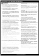
IMPORTANT NOTES AND WARNINGS ! WARNING • This appliance must only be used on a 110 - 230 Volt AC Single Phase electricity supply. • Read all instructions before installing or using this heater • • Use this controller only as described in this manual. Any other use not recommended by the manufacturer may cause fire, electric shock, or injury to persons. This controller is NOT intended to be installed on recreational vehicles and/or boats. • Do not run cord under carpeting.
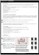
PRODUCT OVERVIEW 1 DESCRIPTION The Wireless Dimmer is suitable for resistive and infrared heaters. The controller allows the power output of the heater to be dimmed down for maximum comfort. The control can be used with 110 - 230VAC supply voltages. 1.1 FEATURES Controls ONE 6500W heater at 230VAC (3400W at 110VAC) or Controls TWO 3200W heaters at 230VAC (1700W at 110VAC). Wireless control with dimming 0% - 100%. Wired control capabilities Configurable soft-start function for increased heater life. 1.
OPERATION 2.2.2 Programming of 7-channel remote 1. Press P1 once and hold down. A continuous beep will sound. 2. While holding the P1 button (during the continuous beep), press a push button on the 7-channel remote that is going to be programmed. The programming is confirmed by an intermittent sound. All buttons are automatically memorised with a preset configuration as in the above drawing. 2.2.3 Programming of 4-channel remote 1. Press P1 twice and hold down. A continuous beep will sound. 2.
OPERATION 2.2.6 Deleting all remote 1. a. b. 2. Press the P2 button two times and hold the P2 button on the second time until the following sound sequence is heard. The will be one beep and then followed by a quick and intermittent sound. Continuous sound. Hearing the sound sequence above indicates that the whole memory of the receiver is deleted. 2.2.7 Deleting a remote from a remote. See remote manual for detail on P3 button. 1. Press the P3 button inside the remote.
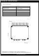
TECHNICAL SPECIFICATIONS WIRELESS CONTROLLER Power Supply 110/230VAC Max Output Power 6500W @ 230VAC 3400W @ 110VAC Fuse Protection 32A (FWC high speed, 10 x 38mm) Reception Frequency 916MHz Operating Temperature Range -20/+30°C Maximum Remote Memorised 42 Dimensions 195 x 200 x 75mm Protection Class IP54 195mm 45mm 200mm Manufactured by Teleco Automation s.r.l. - Italy - www.telecoautomation.
WIRING DIAGRAM RADIO TRANSMISSION INPUT STATUS LED ERROR - LED ON when ACTIVE - Fix : overload - Blinking : overtemperature - When blinking a radio transmission is received Temperature trimmer (see par.8) Safety Lo-Voltage Zone DIP-Switch DANGER Hi-Voltage (see par.1) OUTPUT Level Temperature probe 1 1 2 2 2 3 3 3 4 4 4 5 6 6 7 7 8 8 7 8 T3 T2 T1 T2 T1 T1 T1 T2 T3 Warnings - Hi-Voltage board, risk of electric shock. - Never touch the board outside the safety zone.