BROOKFIELD DIGITAL RHEOMETER MODEL DV-III+ Operating Instructions Manual No. M/98-211-A0701 Please record the Model and Serial Number of your viscometer. Having this information readily available will help us to assist you should there be any questions regarding your instrument. Model No. ______________________ Serial No. ______________________ SPECIALISTS IN THE MEASUREMENT AND CONTROL OF VISCOSITY BROOKFIELD ENGINEERING LABORATORIES, INC.
Contents I. INTRODUCTION ....................................................................................................... 3 I.1 Components ............................................................................................................. 4 I.2 Utilities ..................................................................................................................... 5 I.3 Specifications ....................................................................................................
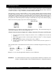
I. INTRODUCTION The Brookfield DV-III+ Programmable Rheometer measures fluid parameters of Shear Stress and Viscosity at given Shear Rates. Viscosity is a measure of a fluid’s resistance to flow. You will find a detailed description of the mathematics of viscosity in the Brookfield publication “More Solutions to Sticky Problems”, a copy of which was included with your DV-III+. The principle of operation of the DV-III+ is to drive a spindle (which is immersed in the test fluid) through a calibrated spring.
I.1 Components Component Part Number DV-III+ Rheometer depends on model Powerbase includes: Leveling Screws (3) Upright Rod Jam Nut Clamp Assembly DVP-2Y VS-3 VS-20 VS-21 VS-27Y Spindle Set with Case LVDV-III+ set of four spindles or RVDV-III+ set of seven spindles or HA/HBDV-III+ set of seven spindles SSL SSR SSH For Cone/Plate versions: a spindle wrench, one cone spindle and sample cup Part No. CPE-44Y replace the spindle set.
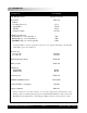
I.2 Utilities Autosensing Power Supply: Input Voltage: 90 - 260 VAC Input Frequency: 50 - 60 Hz Power Consumption: Less than 220 UA Power Cord Color Code: United States Outside United States Black White Green Brown Blue Green/Yellow Hot (live) Neutral Ground (earth) I.3 Specifications Speed Range: 0.01-250 RPM, 0.01 RPM increments from 0.01 to 0.99 RPM, 0.1 RPM increments from 1.0 to 250 RPM Viscosity Accuracy: ± 1.0% of full scale range for a specific spindle running at a specific speed.
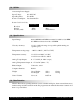
I.5 Set-Up 1) Place the upright rod into the hole at the front of the base. The rack gear and clamp assembly should face the rear of the base (see Figure 1). The upright rod is held in place with the jam nut which is attached from the bottom of the base. Tighten this nut with a suitable wrench (spanner). VS-35 UNIVERSAL CLAMP VS-40Y GEAR SCREW ASSEMBLY VS-41Y CLAMP KNOB ASSEMBLY VS-29 TENSION INSERT VS-28 TENSION SCREW 50S044012E140 4-40 x 3/8 LG. SOC. HD. CAP SCREW VS-29W WASHER (2 REQ'D.
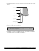
2) Insert the mounting handle on the back of the DV-III+ into the hole on the clamp assembly (Figure 2). Bubble Level Rack Gear Clamp Screw Clamp Assembly Upright Rod Mounting Handle Figure 2 3) Tighten the DV-III+ clamp Screw (Figure 2). Note: If the clamp assembly moves along the upright rod too freely, tighten the tension screw (see Appendix F). 4) Insert the ribbon cable into the DV-III+ Rheometer head.
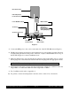
Rheometer Head RTD Temperature Probe Connector Power ON/OFF Switch Ribbon Cable AC Fuse(s) Connector RS-232 Serial Printer/Computer Analog Output(s) AC Power Connector 100-240 VAC 50/60 HZ 220VA MODEL DV-III BASE UNIT Connector Parallel Printer 240 CUSTHING ST. STOUGHTON, MA USA 02072 Connector Ribbon Cable Figure 3 5) Connect the RTD probe to the socket on the back side of the DV-III+ Rheometer (Figure 3). 6) The Rheometer must be leveled before the instrument is zeroed and readings are taken.
I.6 Connections The DV-III+ Rheometer is capable of communicating with several external devices to enhance operation. The cables and connections required for proper communication are detailed below. RHEOLOADER SOFTWARE DVP-80 cable is used to connect the RS232 serial port on the DV-III+ base to Com Port 1 or Com Port 2 on the computer. This cable is supplied with the DV-III+.
I.7 Key Functions Figure 4 shows the control keys on the face of the DV-III+ Rheometer. The following describes each key’s function. MOTOR ON/OFF ESCAPE AUTO RANGE 7 8 9 OPTION TAB PROG 4 5 6 SELECT SPDL PROG RUN 1 2 SELECT DISP PRINT YES . 0 3 NO ENTER Figure 4 MOTOR ON/OFF ESCAPE AUTO RANGE MOTOR ON/OFF, ESCAPE Turns the motor on or off. Cancels any operation, returns the user to the previous screen.
PROG PROG Access the Programs menu for program creation, running or deleting. Contstructs a test program. Allows you to review/modify an existing test program. Execute a Bevis program. PROG RUN PROG RUN Execute DV-III speed/time pair program. 0 NUMBER KEYS (0 through 9) Sets speeds and choose items from various dialog screens and the option menu. ENTER ENTER Functions as an ENTER key similar to a computer by serving to accept a keyboard entry. Brookfield Engineering Laboratories, Inc.
II. GETTING STARTED II.1 Autozero Before readings may be taken, the Rheometer must be autozeroed. This is done each time the power switch is turned on.
II.2 Rheometer Display The DV-III+ Rheometer is supplied with a 4-line display. The basic set of information is called "The Default Screen" and is shown in FIGURE 7. The parameters are detailed below: 1 2 3 4 5 6 Figure 7 1. Motor Status and Current Rheometer Speed The DV-III+ motor can be OFF, ON at 0.0 rpm or ON at a speed greater than 0.0 rpm. When the motor is OFF, "OFF" will be displayed and no speed entry will be accepted. When the motor is ON, the actual speed of rotation will be displayed.
Item Print RPM RPM Model Spindle Torque Viscosity M S T cP or mPas Shear D/CM2 or N/M2 = D/CM2/10 Stress Shear Rate 1/SEC Temperature T T T ii m m ee Z Format Range Example 0.01 <= RPM <= 0.99 X.XX XX.X 0.1 <= RPM <= 99.9 XXX.X 100 <= RPM <= 250 See Model Table D2 - App D XXXXX 00 <= S <= 99 XX -10.1 <= T <= 99.9 XX.X X.XX 0 <= cP <= 9.99 XXX.X 10 <= cP <= 999.9 XXXXX 1000 <= cP <= 99999 XXXeX 100000 <= cP <= 51200000000 X.XX 0 <= D/CM2 <= 9.99 XXX.X 10 <= D/CM2 <= 999.
Figure 9 TORQUE LESS THAN 0% When Rheometer torque drops below zero (0) percent, the Rheometer will continue to display torque values preceded by a minus (-) sign. The viscosity and shear stress field will display dashes (- - - - ) as indicated in the next screen display: Figure 10 II.3 Spindle Entry The user can elect to change the spindle selection by pressing the SELECT SPDL key.
An invalid spindle entry is any two digit number in the range from 01 to 99 which is not listed in Appendix D. This error message will be displayed for a few seconds after which the spindle entry screen (Figure 11) will be re-displayed with a blank field for the spindle number. The user can cancel spindle entry at any time by pressing the MOTOR ON/OFF/ESCAPE key.
Figure 15 Here, the user intends to enter a speed of 112 RPM, has pressed the “1” key twice and is about to press the “2” key. If the user makes more than five (5) key presses, the DV-III+ control program will “roll” the cursor back to the first character of the field and begin to overwrite the previous data entry. Next the user presses the ENTER key to accept the speed.
Figure 18 Figure 19 The DV-III+ may be set to stand alone mode by turning it OFF and ON again and selecting "Stand Alone" or by removing the DVP-80 cable prior to turning the DV-III+ on. Note: The DV-III+ cannot communicate with RHEOLOADER software in the external control mode. Chose "Stand Alone" when presented with Figure 18 if you want to use RHEOLOADER. Brookfield Engineering Laboratories, Inc. Page 18 Manual No.
III. MAKING VISCOSITY MEASUREMENTS III.1 Quick Start The DV-III+ Rheometer uses the same methodology as the Brookfield Dial Reading Viscometer and DV series of Digital Viscometers. If you have experience with other Brookfield equipment, this section will give you the quick steps for taking a viscosity reading. If you have not used a Brookfield Viscometer before, skip this section and go to Section III.2 for a detailed description. A) Assemble and level the rheometer (Section I.5).
III.3 Selecting a Spindle/Speed The DV-III+ has the capability of measuring viscosity over an extremely wide range (for example, the RVDV-III+ can measure fluids within the range of 100-40,000,000 cP) (see Appendix B). This range is achieved through the use of several spindles over many speeds. The process of selecting a spindle and speed for an unknown fluid is normally trial and error. An appropriate selection will result in measurements made between 10-100 on the instrument % torque scale.
IV. PROGRAMMING THE DV-III+ AND ANALYSIS The programming and data analysis functions of the DV-III+ are accessed by pressing the PROG key on the rheometer. The display will change to present a menu with three choices: DV-III, B.E.V.I.S., and Models. DV-III and B.E.V.I.S. are the programming alternatives. Models will present the five math models available for data analysis. Figure 20 IV.1 Programming Concept The DV-III+ may be programmed to collect viscosity data without operator involvement.
IV.2 DV-III Speed/Time Pair Programming This programming method allows the operator to control the DV-III+ through the variables of speed and time. These speed/time pairs instruct the rheometer to operate at a speed of rotation for a certain period of time. Programs can be created with up to 25 steps. The DV-III+ can store up to 10 programs. Upon completion of a program, the data may be viewed on the DV-III+ display, analyzed or printed to an attached parallel or serial printer.
Figure 21 At this point, the user may Enter/Edit, Clear or Use a stored program (Speed Set). Let’s startwith Enter/Edit by pressing the “1” key: Figure 22 In this example, the user is informed that he has 6 speed sets (0,1,2,5,8,9) pre-programmed in memory and 4 speed sets (3,4,6,7) not programmed and available. Select any one of the ten speed sets by pressing the appropriate numeric key.
The OPTION/TAB key is used for moving from input field to input field and the ENTER key to accept the current input for a step. On entry to this screen, the underscore cursor would be flashing (as shown) under the first digit of the step RPM. Use the numeric keys to make changes to the step speed, repeating the input as many times as required until satisfied. When satisfied with the speed input, press the OPTION/TAB key which moves the flashing cursor down to the first character of the time field.
The program is initiated by pressing the PROG RUN key. See "Using Pre-programmed Speeds." SPEED SETS WITH ZERO STEP TIMES These programs when executed will require that the user press the ENTER key to progress from step to step. On pressing the “3” key in Figure 22 the user is presented with the same screen that he saw in the above description for finite step programs: Figure 27 The user inputs his step RPM exactly as he did for finite step time programs above.
Figure 29 This message simply asks the user to make sure the printer is ready (it’s on-line and has paper in it) and then awaits for the PRINT key to be pressed.
This screen advises that there are 7 speed sets in memory; speed set #3 is in use and that the DVIII+ is awaiting input for the speed set to delete. Note: If no speed set is in use the word “NONE” will appear next to the IN USE: prompt. At this point, the user has two options: 1. Pressing the MOTOR ON/OFF/ESCAPE key will exit from this screen and no speed sets will be cleared. Or 2. Pressing any of the keys “0”, “1”, “2”, “3”, “5”, “8”, or “9” will delete that speed set.
Figure 33 However, we will assume at this point that we have selected speed set #2 for use in the ensuing data gathering operations. To initiate the use of this speed set (with finite step times or with zero step times), the user presses the PROG RUN key and is presented with a start/end step input screen as shown next: Figure 34 If the user had not previously entered start and end steps, this screen will display 01 for the start step, and the last program step (13 in this case) as the end step.
Figure 36 LOCKOUT OPTIONS Pressing the “1” key locks out any use of the NUMERIC keys, and the PROGRAM, SELECT SPINDLE and OPTIONS/TAB keys. Pressing the “3” key would disable an existing lockout condition only when in the LOCKOUT OPTIONS screen, Figure 36. After pressing the “1” or “3” keys the user would be returned to the display of Figure 34.
USING PROGRAMMED SPEEDS WITH A ZERO TIME INTERVAL Assume the following: • • • • A speed set has been selected. A subset of the speed set has not been selected. (i.e. we will use the entire set of speeds) The speed set included a time interval that was equal to zero minutes and zero seconds. Print mode has been set to non-continuous mode (i.e. output will be sent to the printer only when the user presses the ENTER key).
Figure 41 Pressing the ENTER key would return the user to the default screen, as depicted in Figure 40, or to the program start and stop limit selections of Figure 34 if the PROG RUN key is pressed. USING PROGRAMMED SPEEDS WITH A NON-ZERO TIME INTERVAL Assume the following: • • • • A speed set has been selected. A subset of the speed set has not been selected. (i.e.
Figure 43 Pressing the ENTER key would return the user to the default screen, as depicted in its general form in Figure 42, or to the program start and stop limit selections of Figure 34 if the PROG RUN key is pressed.
The step number would be incremented each time the user pressed the ENTER key. Assume that the speed corresponding to step #04 was executing. If the user presses the ENTER key, our display will be updated as shown in Figure 47 Figure 47 PROGRAMMED SPEED STOP The user may stop program mode operation at any time by pressing the MOTOR ON/OFF/ESCAPE key anytime during program operation.
IV.3 Bevis Programs The B.E.V.I.S. Programming Method allows the operator to control the DV-III+ through the variables of speed, temperature and time while providing for independent data collection. Programs can include up to 25 commands with a maximum data count of 800. The DV-III+ can store up to 10 programs. Upon completion of the program the data may be viewed on the DVIII+ display, analyzed or printed to an attached parallel or serial printer. B.E.V.I.S.
program slot for use. The above screen would be updated to reflect the new selection. A press of the 5,6,7,8 or 9 keys will place the user in the B.E.V.I.S. program download mode. The following screen appears (assuming a press of the “5” key): Figure 52 The user’s selection “5” is flashing and is the current slot selection. When ready, the user presses the ENTER key to begin the program download. The following screen will appear for the duration of the download. See Section VI.
step, the total number of steps (02/39) and any time intervals if they are relevant. The WKY command message could be displayed on the bottom line in lieu of the step and time info. This screen stays resident until the user presses the OPTIONS/TAB key which “toggles” back-and-forth between this screen and an amended default screen shown next: Figure 56 The user now sees viscosity data and can use the SELECT DISPLAY key to view other viscosity measurement parameters.
IV.5 Data Analysis Data collected from DV-III speed/time pairs or B.E.V.I.S. programs may be analyzed using several math models. These models provide a means to numerically describe the behavior of the test fluid. In the case of viscosity measurement, a non-Newtonian fluid will produce a curve when test data is plotted on a shear stress vs. shear rate graph. The math model will force the data into a straight line and describe it with a slope and y intercept.
The user is informed that there are five (5) math models which can be used on the buffer data. A model is selected by pressing the appropriate numeric key. No matter the model selected, the following screen will be displayed for the duration of the mathematical analysis: Figure 59 When the calculations are complete, the results for the particular model will be displayed as follows: Figure 60 This screen, for the Standard CASSON Model, is typical for all five (5) of the math models.
1. Casson (Standard) The Standard Casson equation is: √τ = √τo τo = Shear Stress τo = Yield Stress (stress at zero shear rate) ηD = Plastic Viscosity D = Shear Rate + √ηD where: The calculated parameters for this model are: Plastic Viscosity (cP or mPa•s) Yield Stress (Dynes/cm2 or N/m2) Confidence of Fit (%) The Standard Casson method is a direct implementation of the original Casson equation. 2.
The calculated parameters for this model are: Flow Index (no units) Consistency Index (cP or mPa•s) Confidence of Fit (%) 5. IPC Paste Analysis This method is intended to calculate the Shear Sensitivity Factor and the 10 RPM Viscosity value of pastes. A prime example of its use is in the solder paste industry, thus the name IPC (Institute for Interconnecting and Packaging Electronic Circuits).
3. Change communication status with external Brookfield temperature controller. An "off" indication means that there is no communication with a controller. Selecting this option will make the DV-III+ try to establish communication. When communication is established, "off" will be change to "on". Temperature control will always be set to "off" when the DV-III+ is turned on. When communication is established, Line 1 of the default screen will be modified.
V.3 Alarms There are three adjustable alarm settings: LO ALARM %, HI ALARM % and MOTOR OFF %. The values are set in the Set Alarms mode. Alarms are used to signal the operator that the fluid is out of the input specification. The alarms are set in % torque values, not Viscosity, Shear Stress or Shear Rate values. The range of values which may be entered for each alarm and their default values are: LO ALARM HI ALARM MOTOR OFF Minimum value: 10% Maximum value: 99.
V.4 Set Temperature The DV-III+ can issue temperature control commands when an external temperature control device has been connected (see Section V.1). Selecting item #4 Set Temp in the Options menu will display the current setpoint. Enter the new setpoint by using the number keys and accept with the ENTER key. The temperature controller will begin using the new setpoint immediately upon the press of the ENTER key.
Sample Name:_____________________________________________________________ Operater Name:____________________________ Date: 06/21/91 Time: 10:06 Model: 2R Spindle: 31 #01 RPM=30.0 #02 RPM=40.0 #03 RPM=50.0 #04 RPM=60.0 #05 RPM=70.0 %=18.2 %=24.3 %=30.3 %=36.3 %=42.3 cP=970 cP=972 cP=969 cP=967 cP=966 D/CM2=100 D/CM2=132 D/CM2=164 D/CM2=197 D/CM2=230 1/SEC=10.2 1/SEC=13.6 1/SEC=17.0 1/SEC=20.4 1/SEC=23.8 T=22.1C T=22.1C T=22.1C T=22.1C T=22.
Figure 65 Note: If continuous printing was used during the test, it will be suspended when viewing the test data or entering time to torque parameters. TIMED STOP The DV-III+ will operate at a single RPM for a specified period of time. Time and speed are entered using the number keys and OPTIONS/TAB key. The test will begin immediately upon the press of the ENTER key. The test will end when the specified time interval has elapsed. The data will be shown as displayed in Figure 66.
Figure 67 Note: Printing during a Timed Average test will show non-averaged data. Averaged data is available only at the conclusion of the test. Printing the averaged data must be done with the PRINT key at the end of the test. Brookfield Engineering Laboratories, Inc. Page 46 Manual No.
VI. Rheoloader User's Manual B.E.V.I.S. (Brookfield Engineering Rheometer Instruction Set) is a scripting language developed at Brookfield Engineering Laboratories that allows for the creation of flexible programs to control our line of Rheometers. In the case of the DV-III+ Rheometer, programs are created then loaded into the Rheometer using the RheoLoader software. Some features of the scripting language are: • Repeatedly run the same program for quality control purposes.
By using various combinations of the above commands, programs are created that automatically control the viscometer and collect data (via an attached printer) from the DV-III+ Rheometer. The RheoLoader software is a Windows 95 (or above) based program used to create, save, print and downlaod B.E.V.I.S. programs to the DV-III+ Rheometer. Start the software by clicking on its associated icon or by clicking the Start button; select Run; enter the name of the progrram to execute {Rheoad.exe}; then click OK.
Click the Delete button to delete the command in the selected row of the program grid. Click the Up button to move the command in the selected row of the program grid up one row. Click the Down button to move the command in the selected row of the program grid down one row. Click the Clear button to clear the grid of all commands. Once cleared, the commands cannot be retrieved. This list box displayed the commands available for creating programs.
B.E.V.I.S. PROGRAM TO SLOT #1. Click on this button to download the displayed program to the DV-III+. When the download is complete, the DV-III+ displays DOWNLOAD DONE TO EXIT PRESS A KEY. At this point, the program in the DV-III+ can be printed and/or run from the Rheometer. Click on this button to exit the RheoLoader software. VI.
Program 4: Command Spring relax Command Description Parameter WKY Wait for a key press Wind to 100% WPT Wait for % torque 100.0 WKY Wait for a key press Release spindle SPI Set print interval 00:01 WPT Wait for % torque 0.
APPENDIX A - Cone/Plate Rheometer Set-Up This Cone/Plate version of the DV-III+ uses the same operating instruction procedures as described in this manual. However, the “gap” between the cone and the plate must be verified/adjusted before measurements are made. This is done by moving the plate (built into the sample cup) up towards the cone until the pin in the center of the cone touches the surface of the plate, and then by separating (lowering) the plate 0.0005 inch (0.013mm).
A.2 SETUP 1. Be sure that the Viscometer is securely mounted to the Laboratory Stand, leveled and zeroed with no cone or cup attached and 0% torque is displayed. Bath Outlet 2. Figure A2 shows a typical water bath setup. Connect the sample cup inlet/outlet ports to the water bath inlet and outlet and set the bath to the desired test temperature. Allow sufficient time for the bath to reach the test temperature. 3.
A.3 SETTING THE GAP 1. Move the toggle switch to the right; this will turn on (enable) the Gap Setting Feature. The Pilot (red) light will be illuminated. 2. If the contact light (yellow) is illuminated, turn the micrometer adjustment ring clockwise (as you look down on the instrument) until the light is just breaking contact, i.e., flickering (see Figure A5). Moves Away Moves Towards from Hit Point Hit Point (clockwise) (counter-clockwise) LEFTx RIGHT 3.
A.4 VERIFYING CALIBRATION 1. Determine the appropriate sample volume. Refer to Table A1 to determine the correct sample volume required for the spindle to be utilized. Ta b l e A 6 Cone Part No. S a m p l e Vo l u m e CPE-40 CPE-41 CPE-42 CPE-51 CPE-52 2. Select a Brookfield Viscosity Standard fluid that will give viscosity readings between 10% and 100% of full scale range. Refer to Appendix B for viscosity ranges of cone spindles; ranges listed apply to CPE cones. 0.5 2.0 1.0 0.5 0.
APPENDIX B - Viscosity Ranges The table below (Universal Spindle Ranges) lists the Spindle Range Coefficients for all spindles used on DV-III+ Rheometers. Dividing the coefficient number by any of the 2,500 Rheometer speeds will give the full scale viscosity range for a Rheometer/spindle/speed combination.
Universal Spindle Ranges SPINDLE RANGE COEFFICIENT Spindle Entry Code Rheometer Series LV RV HA HB DIN-81 DIN-82 DIN-83 DIN-85 DIN-86 81 82 83 85 86 3,420 3,420 11,340 1,144 3,420 36,500 36,500 121,300 12,200 36,500 73,000 73,000 242,600 24,400 73,000 292,000 292,000 970,400 97,600 292,000 SC4-14 SC4-15 SC4-16 SC4-18 SC4-21 SC4-25 SC4-27 SC4-28 SC4-29 SC4-31 SC4-34 SC4-37 14 15 16 18 21 25 27 28 29 31 34 37 117,200 46,880 120,000 3,000 4,688 480,000 23,4000 46,8880 93,750 30,000 60,000 23,400
LV(#1-4) and RV,HA,HB(#1-7) Rheometers Viscosity Range (cP) Viscometer Minimum LVDV-III+ RVDV-III+ HADV-III+ HBDV-III+ Maximum 15 100 200 800 6,000,000 40,000,000 80,000,000 320,000,000 Small Sample Adapter Spindle 14 15 16 18 21 25 27 28 29 31 34 37 82 83 Shear Rate (sec-1) 0 0 0 0 0 0 0 0 0 0 0 0 0 0 - Viscosity (cP) LVDV-III+cP 80 47.0 - 1,171,000 96 19.0 - 468,650 58 48.0 - 1,199,700 264 1.3 30,000 186 1.9 46,865 44 192.0 - 4,790,000 68 9.4 - 234,325 56 18.8 - 468,650 50 37.5 - 937,300 68 12.
Din Adapter Spiral DAA Spindle Shear Rate (sec-1) LVDV-III+ RVDV-III+ HADV-III+ HBDV-III+ 85 86 87 0 - 258 0 - 258 0 - 258 0.6 - 5,000 1.8 - 10,000 5.7 - 50,000 6.1 - 5,000 18.2 - 10,000 61.0 - 50,000 12.2 - 5,000 36.5 - 10,000 121 - 50,000 48.8 - 5,000 146 - 10,000 485 - 50,000 Viscosity (cP) Adapter Spiral Spindle SA-70 Viscosity (cP) Shear Rate (sec-1) .677 - 67.7 LVDV-III+ RVDV-III+ HADV-III+ HBDV-III+ 98.
full scale range precision of (+/-) 1% of any spindle/speed combination. We discourage taking readings below 10% of range because the potential viscosity error of (+/-) 1% is a relatively high number compared to the instrument reading. The second consideration involves the mechanics of fluid flow. All rheological measurements of fluid flow properties should be made under laminar flow conditions. Laminar flow is flow wherein all particle movement is in layers directed by the shearing force.
APPENDIX C - Variables in Viscosity Measurements As with any instrument, there are variables that can affect a viscosity measurement. These variables may be related to the instrument (Rheometer) or the test fluid. Variables related to the test fluid deal with the rheological properties of the fluid, while instrument variables would include the Rheometer design and the spindle geometry system utilized.
A repeatable viscosity test should control or specify the following: 1) 2) 3) 4) 5) 6) 7) Test temperature Sample container size (or spindle/chamber geometry) Sample volume Rheometer model Spindle used (if using LVDV-III+(#1-4) or RVDV-III+(#1-7) attach the guard leg) Test speed or speeds (or the shear rate) Length of time or number of spindle revolutions to record viscosity. Brookfield Engineering Laboratories, Inc. Page 62 Manual No.
APPENDIX D - Spindle and Model Codes Each spindle has a two digit code which is entered using the SPDL key on the DV-III+ key pad. The entry code allows the DV-III+ to calculate Viscosity, Shear Rate and Shear Stress values. Each spindle has two constants which are used in these calculations. The Spindle Multiplier Constant (SMC) used for viscosity calculations, and the Shear Rate Constant (SRC), used for shear rate and shear stress calculations.
Table D1 (continued) SPINDLE ENTRY CODE SC4-27 27 SC4-28 28 SC4-29 29 SC4-31 31 SC4-34 34 SC4-37 37 CP40 40 CP41 41 CP42 42 CP51 51 CP52 52 Spiral Adapter 70 Thermosel DIN spindle 81 SSA DIN spindle for 13R or 13RP chamber 82 SSA DIN spindle for 7R or 7RP chamber 83 ULA DIN spindle 85 ULA DIN spindle 86 ULA DIN spindle 87 SMC 25 50 100 32 64 25 0.327 1.228 0.64 5.12 9.83 105 3.7 SRC 0.34 0.28 0.25 0.34 0.28 0.36 7.5 2 3.8 3.84 2 0.677 1.29 3.75 1.29 12.09 1.22 3.65 12.13 1.29 1.29 1.29 1.
The Shear Rate calculation is: Shear Rate (1/sec) = SRC * RPM where: SRC = Shear Rate Constant from Table D1 Using Non-standard spindles with DV-III+ and RHEOCALC Software Spindle Entry 99 allows entry of spindle constants which the DV-III+ will use to calculate Viscosity, Shear Rate and Shear Stress for spindles in boundary conditions other than the 600ml beaker or specified chamber. The spindles must conform to geometries that allow for mathematical calculations of Shear Rate and Shear Stress i.e.
where: = Radius of the container (in centimeters) = Radius of the spindle (in centimeters) χ = Radius at which the shear rate is to be calculated (normally the same value as Rb; in centimeters) ω = Angular velocity of the spindle (Rad/Sec) 2π * ω= N 60 Rc Rb N = Spindle speed in RPM SMC and SRC values are entered in RHEOCALC software. See the HELP file for details. Brookfield Engineering Laboratories, Inc. Page 66 Manual No.
APPENDIX E - Calibration Procedures The accuracy of the DV-III+ is verified using viscosity standard fluids which are available from Brookfield Engineering Laboratories or your local Brookfield agent. Viscosity standards are Newtonian, and therefore, have the same viscosity regardless of spindle speed (or shear rate). Viscosity standards, calibrated at 25°C, are shown in Table E1. Container size: For Viscosity Standards < 30,000 cP, use a 600 ml Low Form Griffin Beaker having a working volume of 500 ml.
Brookfield Viscosity Standard Fluid - General Information We recommend that Brookfield Viscosity Standard Fluids be replaced on an annual basis, one year from date of initial use. These fluids are pure silicone and are not subject to change over time. However, exposure to outside contaminants through normal use requires replacement on an annual basis. Contamination may occur by the introduction of solvent, standard of different viscosity or other foreign material.
3) Put the spindle into the test fluid and attach the extension link, coupling nut and free hanging spindle (or directly attach the solid shaft spindle) to the DV-III+. 4) Allow 30 minutes for the viscosity standard, sample chamber and spindle to reach test temperature. 5) Measure the viscosity and record the Rheometer reading. Note: The spindle must rotate at least five (5) times before a viscosity reading is taken.
Calibration Procedure using a Helipath Stand and T-Bar Spindles When a Helipath Stand and T-Bar spindles are used: Remove the T-bar spindle and select a standard LV(#1-4) or RV,HA,HB(#1-7) spindle. Follow the procedures for LV(#1-4) and RV,HA,HB (#1-7) Brookfield spindles outlined above. T-Bar spindles should not be used for verifying calibration of the DV-III+ Rheometer. Calibration Procedure for Spiral Adapter 1) Place the viscosity standard fluid (in the proper container) into the water bath.
4) With the viscometer stopped, remove the sample cup and place the viscosity standard fluid into the cup, waiting 10 minutes for temperature equilibrium. 5) Connect the sample cup to the Rheometer. Allow sufficient time for temperature to reach equilibrium. Typically 15 minutes is the maximum time that you must wait. Less time is required if spindle and cup are already at test temperature. 6) Measure the viscosity and record the Rheometer reading in both % torque and centipoise (cP).
The Brookfield Guardleg The guard leg was originally designed to protect the spindle during use. The first applications of the Brookfield Viscometer included hand held operation while measuring fluids in a 55 gallon drum. It is clear that under those conditions the potential for damage to the spindle was great. Original construction included a sleeve that protected the spindle from side impact.
accurate and repeatable torque reading under any measurement circumstance. However, the conversion of this torque reading to centipoise will only be correct if the factor used was developed for those specific conditions. Brookfield has outlined a method for recalibrating a Brookfield Viscometer/Rheometer to any measurement circumstance in More Solutions to Sticky Problems, Section 3.3.10.
APPENDIX F - VS-27Y Clamp Assembly The VS-35Y Clamp assembly holds the DV-III+ on the upright rod and thus supports it on the base. The parts are shown in Figure F1. VS-41Y Clamp Screw Assembly VS-29 Tension Insert VS-29W Washers VS-28 Tension Screw Figure F1 If the clamp is taken off the upright rod, the tension insert (Part No. VS-29) must be properly aligned for the clamp to fit back onto the upright rod. When the tension insert (Part No.
APPENDIX G - DV-III+ to Computer Command Set The command set used to communicate with the DV-III+ is as follows: Command Format from Host E(nable) R(etrieve) V(elocity) I(dentify) Z(ero) Illegal String Response from Rheometer Description Enable control circuitry Retrieve data Send speed Identify instrument Zero instrument Invalid command Where: qqq
Model LV 2.5LV 5LV RV RV RV HA 2HA 2.5HA HB 2HB 2.
APPENDIX H - Fault Diagnosis and Troubleshooting Listed are some of the more common problems that you may encounter while using your rheometer. ❏ Spindle Does Not Rotate ✓ Make sure the rheometer is plugged in. ✓ Check the voltage rating on your rheometer (115V or 220V); it must match the wall voltage. ✓ Make sure the motor is ON and the desired rpm is selected. ❏ Spindle Wobbles When Rotating or Looks Bent ✓ Make sure the spindle is tightened securely to the rheometer coupling.
❏ Viscometer Will Not Return to Zero ✓ Rheometer is not level • Adjust the laboratory stand ✓ Pivot point or jewel bearing faulty • Perform calibration check • Contact Brookfield Engineering Laboratories, Inc. or your Brookfield dealer for repair. ❏ Inaccurate Readings ✓ Verify spindle, speed and model selection. ✓ If % readings are under-range (less than 10%), the units display (%, cP, D/cm2, 1/sec) will flash; change spindle and/or speed.
❏ No Recorder Response ✓ Be sure the rheometer is not at ZERO reading. ✓ Be sure the recorder is ON and not on STANDBY. ✓ Verify the range settings. ✓ Check cable leads for clean connection.
APPENDIX I - Warranty Repair and Service Warranty Brookfield Viscometers are guaranteed for one year from date of purchase against defects in materials and workmanship. They are certified against primary viscosity standards traceable to the National Institute of Standards and Technology (NIST). The Viscometer must be returned to Brookfield Engineering Laboratories, Inc. or the Brookfield dealer from whom it was purchased for no charge warranty service. Transportation is at the purchaser’s expense.
a Packaging Instructions to Return a Viscometer for Repair or Calibration ❏ Remove and return all spindles (properly packed for shipping). ❏ Clean excess testing material off the instrument. F I G U R E K 1 ❏ Include MSDS sheets for all materials tested with this instrument. ❏ Support pointer shaft with white, nylon shipping cap, as shown in Figure K1, or with white plastic shipping cap originally supplied with instrument. ❏ Pack the instrument in its original case.
Providing us with the following information will help us to service your equipment more quickly and efficiently. Please photocopy, fill out and return a copy of this form with your instrument. Brookfield recommends that all viscometers be returned for annual calibration to ensure that your equipment continues to provide the same accuracy you have come to expect from Brookfield products.
Brookfield Engineering Laboratories, Inc. Page 83 MODEL SPINDLE RPM DIAL READING % TORQUE FACTOR BY: VISCOSITY cP SHEAR RATE TEMP °C FOR: TIME NOTES BROOKFIELD ENGINEERING LABORATORIES, INC. • 11 Commerce Boulevard • Middleboro, MA 02346 • TEL: 508-946-6200 or 800-628-8139 (USA ex MA) FAX: 508-946-6262 • www.brookfieldengineering.com CONCLUSIONS: SAMPLE TEST INFORMATION: VISCOSITY TEST REPORT DATE: This tear-off sheet is a typical example of recorded test data.