
Owner manual


Brookfield Engineering Laboratories, Inc. Page 6 Manual No. M/98-211-A0701
I.5 Set-Up
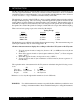
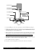
1) Place the upright rod into the hole at the front of the base. The rack gear and clamp assembly
should face the rear of the base (see Figure 1). The upright rod is held in place with the jam nut
which is attached from the bottom of the base. Tighten this nut with a suitable wrench (spanner).
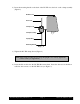
Figure 1
BASE UNIT
VS-41Y
CLAMP KNOB
ASSEMBLY
50S044012E140
4-40 x 3/8 LG.
SOC. HD. CAP SCREW
VS-35
UNIVERSAL
CLAMP
VS-40Y
GEAR SCREW
ASSEMBLY
VS-29
TENSION
INSERT
VS-28
TENSION
SCREW
VS-29W
WASHER
(2 REQ'D.)
VS-34
UPRIGHT ROD
502020032S34Z
WASHER, EXT. TOOTH,
5/16 O.D. x 5/32 I.D.
50S311B24S06B, SCREW,
5/16 - 18x3/8 LG. SLT. PAN HD.