
Owner manual


Brookfield Engineering Laboratories, Inc. Page 8 Manual No. M/98-211-A0701
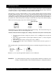
Figure 3
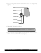
5) Connect the RTD probe to the socket on the back side of the DV-III+ Rheometer (Figure 3).
6) The Rheometer must be leveled before the instrument is zeroed and readings are taken. The level
is adjusted using the three leveling screws on the base. Adjust so that the bubble level on top of
the DV-III+ (Figure 2) is centered within the circle.
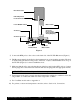
7) Make sure that the AC power switch at the rear of the base unit is in the OFF position. Connect
the AC plug to the socket on the back of the DV-III+ base and plug it into the appropriate AC line.
The DV-III+ must be earth grounded to ensure against electronic failure!!
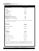
8) Temperature monitoring is assured (after the instrument has stabilized) to within ±1.0°C in the
range -100°C to +150°C and within 2°C in the range 150°C to 300°C.
9) For Cone/Plate models refer to Appendix A.
10) For printers, software and temperature controllers, refer to Section 1.6, Connections.
100-240 VAC 50/60 HZ 220VA
MODEL DV-III BASE UNIT
240 CUSTHING ST.
STOUGHTON, MA USA 02072
Rheometer Head
RTD Temperature
Probe Connector
Power ON/OFF Switch
AC Fuse(s)
AC Power Connector
Connector Connector
Parallel Printer Ribbon Cable
Ribbon Cable
Connector
RS-232 Serial
Printer/Computer
Analog Output(s)