BROOKFIELD DV2T Viscometer Operating Instructions Manual No. M13-167-B0614 SPECIALISTS IN THE MEASUREMENT AND CONTROL OF VISCOSITY with offices in: Boston • Chicago • London • Stuttgart • Guangzhou BROOKFIELD ENGINEERING LABORATORIES, INC. 11 Commerce Boulevard, Middleboro, MA 02346 USA TEL 508-946-6200 or 800-628-8139 (USA excluding MA) FAX 508-946-6262 INTERNET http://www.brookfieldengineering.
Table of Contents I. INTRODUCTION.......................................................................................... 5 I.1 Components................................................................................................................ 6 I.2 Utilities........................................................................................................................ 8 I.3 Specifications......................................................................................................
IV.4.3 Set Time and Date................................................................................... 52 IV.4.4 Backup and Import................................................................................... 52 IV.4.5 Default Path............................................................................................. 53 IV.4.6 Settings Reset..........................................................................................
I. INTRODUCTION The Brookfield DV-II Viscometer series has been the leading industrial viscometer since it was first introduced in 1985. Brookfield has continued to develop and improve the DV-II to provide the best value in the market for both quality control and research customers. The Brookfield DV2T Viscometer continues in this tradition of innovation, quality and value.
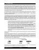
All units of measurement are displayed according to either the CGS system or the SI system. 1. Viscosity appears in units of centipoise (cP), Poise (P), milliPascal-seconds (mPa•s) or Pascal-seconds (Pa•s) on the DV2T Viscometer display or centistokes (cSt) or millimeter squared per second (mm2/sec). 2. Shear Stress appears in units of dynes/square centimeter (D/cm2) or Newtons/ square meter (N/m2)/or Pascals (Pa). 3. Shear Rate appears in units of reciprocal seconds (1/sec). 4.
COMPONENT DIAGRAM DV2T Viscometer Model G Laboratory Stand Bubble Level Spindle Set Shipping Cap Guard Leg LV Spindle Set shown above Leveling Screw Cone/Plate Option Temperature Probe Wrench Temperature Probe Clip Toggle Switch for Electronic Gap Tension Bar Cone Spindle Sample Cup Temperature Probe Figure I-1 Brookfield Engineering Labs., Inc. Page 7 Manual No.
I.2 Utilities Input Voltage: Input Frequency: Power Consumption: Power Cord Color Code: Hot (live) Neutral Ground (earth) Universal Power Supply (90-264 VAC) 50/60 Hz 150 VA United States Black White Green Outside United States Brown Blue Green/Yellow Main supply voltage fluctuations are not to exceed ±10% of the nominal supply voltage. I.3 Specifications Speeds: 0.1 - 200 RPM Weight: Gross Weight: 23 lbs. 10.5 kg. Net Weight: 20 lbs.
Electrical Certifications: Conforms to CE Standards: BSEN 61326: Electrical equipment for measurement, control and laboratory use - EMC requirements BSEN 61010-1: Safety requirements for electrical equipment, for measurement, control and laboratory use Notice to customers: This symbol indicates that this product is to be recycled at an appropriate collection center.
7) Make sure that the AC power switch at the rear of the DV2T is in the OFF position. Connect the power cord to the socket on the back panel of the instrument and plug it into the appropriate AC line. For Cone/Plate Models, be sure that the toggle switch, used to activate the electronic gap, is to the left position. (Left when facing the viscometer.
I.5 Safety Symbols and Precautions Safety Symbols The following explains safety symbols which may be found in this operating manual. Indicates hazardous voltages may be present. Refer to the manual for specific warning or caution information to avoid personal injury or damage to the instrument. Precautions If this instrument is used in a manner not specified by the manufacturer, the protection provided by the instrument may be impaired.
Status Bar: The Status Bar provides information relating to the date and time (as configured by the user) and various connections to the DV2T Viscometer. Test Name: The Test Name identifies the name of the currently loaded test. Title Bar: The Title Bar identifies the activity to be conducted in the current view and includes any navigation icons that are relevant. Data Fields: The Data Fields include measurement results and test parameters.
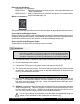
II. GETTING STARTED II.1 Power Up The DV2T will go through a Power Up sequence when the power is turned on. The Viscometer will issue a beep, present a blue screen, and finally show the DV2T About screen for 5 seconds. The About screen is shown below and includes several critical parameters about the viscometer including; viscometer torque (LV, RV, HA, HB, or other), firmware version number, model number (DV2TLV for example) and the serial number.
Figure II-2 The operator must ensure that the viscometer is level (see Section I.4) and remove any attached spindle or coupling. When the Next button is pressed, the viscometer will operate for approximately 13 seconds. After the AutoZero is complete and the operator presses the Next button, the viscometer will transition to the Configure Viscosity Test screen. If the AutoZero was performed from the Settings Menu, then the viscometer will return to the Settings Menu.
II.4 Navigation The DV2T Viscometer uses a touch screen display. Navigation of the instrument features is done using a variety of Data Fields, Arrows, Command Keys and Navigation Icons. The operating system has been designed for intuitive operation and employs color to assist the user in identifying options. Data Fields require that the user touch the screen to initiate the data entry / selection process. These fields are normally outlined in black. They may also include a blue arrow.
II.5 Home Screen . The Home screen The DV2T Home screen can be accessed by using the Home Icon shows the Main Menu functions and provides access to User Log In and Settings (see Section II.4). Figure II-3 Configure Viscosity Test: Create and Run viscosity tests. Load Test: Load a test that has previously been saved or created with PG Flash software. Tests may be loaded from internal memory or a USB Flash Drive. View Results: Load Results (saved test data) that have previously been saved.
Status Bar Title Bar Test Name Test Parameters More/Less Bar Command Keys Figure II-4 The user can see the name of any test that has been loaded through the Load Test function. In Figure II-4, the file name is listed as Unsaved Test, indicating that the current test has not been saved. The More/Less bar is seen just below the test parameters. In Figure II-4, this bar includes a down arrow, which indicates that more information is available.
Torque: A live signal from the viscometer. Spindle: The currently selected spindle. All viscosity, shear rate, and shear stress calculations will be made based on this spindle. The spindle number may be changed by pressing the blue arrow. Speed: The currently selected speed of rotation. The viscometer will operate at this speed once the RUN command key is pressed. The speed may be changed by pressing the blue arrow.
II.5.3 View Results Test results (data files) can be saved to the internal memory of the DV2T or to a USB Flash Drive. Theses files can be reloaded into the DV2T for review, analysis, or printing through the View Results function. A file of Test Results that is saved onto a USB Flash Drive can be viewed on any DV2T Viscometer. Within the View Results function, the user can access the internal memory of the DV2T .
Range Figure II-6 TIP: The Range value is the same as the AutoRange available on earlier Brookfield viscometer models. II.7 Out of Range The DV2T Viscometer will give on screen indications when the measurement is out of range of the instrument. When the %Torque reading exceeds 100% (over range), the display of %Torque, Viscosity, and Shear Stress will be EEEE (see Figure II-7). If the %Torque value is between 0 - 9.9%, the data field label will flash.
Measurement data should not be collected when the %Torque reading is out of range. The out of range condition can be resolved by either changing the speed (reduce speed when reading is out of range: high) or changing the spindle (increase the spindle size when the reading is out of range: low). TIP: When comparing data, the test method is critical. Be sure that you know the proper spindle and speed required for the test method.
Printer format is detailed below: Data Label (Small) Data Label (Large) TIP: When printing to a label, if the data set includes more than one point, only the last point will be printed. Data Continuous Brookfield Engineering Labs., Inc. Page 22 Manual No.
III. MAKING VISCOSITY MEASUREMENTS III.1 Quick Start The DV2T Viscometer uses the same methodology for viscosity measurements as the Brookfield Dial Reading Viscometers and DV series of Digital Viscometers. If you have experience with other Brookfield equipment, this section will give you quick steps for taking a viscosity reading. If you have not used a Brookfield Viscometer before, skip this section and go to Section III.2 for a detailed description.
Many samples must be controlled to a specific temperature for viscosity measurement. When conditioning a sample for temperature, be sure to temperature control the container and spindle as well as the sample. Please see our publication, “More Solutions to Sticky Problems”, for more detail relating to sample preparation. III.3 Selecting a Spindle/Speed The DV2T has the capability of measuring viscosity over an extremely wide range.
If your instrument has the EZ-Lock system, the spindles are attached as follows: With one hand hold the spindle, while gently raising the springloaded outer sleeve to its highest position with the other hand, as shown in Figure III-2. Insert the EZ-Lock Spindle Coupling so that the bottom of the coupling is flush with the bottom of the shaft, and lower the sleeve. The sleeve should easily slide back down to hold the spindle/coupling assembly in place for use.
Figure III-3 Figure III-4 Single Point: Collect only a single data point when the End Condition is met. Single Point Averaging: Specify an amount of time over which to average measured data. Collect a single data point when the End Condition is met. This data point is an averaged value. If the time for averaging is shorter than the total time for the step, then the average will be performed for the specified time at the end of the test.
Multi Point: Collect multiple data points based on time. The Data Interval is specified in Hours:Mins:Secs. If the End Condition is set to Time, then the total number of points will be calculated and displayed in the Data Collection screen. If the End Condition is not based on time then it is possible that the step will conclude prior to a data point being collected.
Collect Single Point at Step End. During the test, the total time required to reach 200 cP is 10 minutes 40 seconds. Total points collected will be 11 with the last data point taken at 10 minutes 40 seconds, an average of the last 20 seconds of the step. No Data: End Condition is met and no data is collected. III.6 End Condition The completion of a test is defined by the End Condition. Each time that you enter Configure Viscosity Test, the End Condition will be set to the last value used.
then rerunning the test (see Section III.8). This method can allow you to quickly evaluate the spindle selection to determine the best speeds for testing. # of Points: The test will complete when the specified number of data points has been collected. Data is collected according to the Data Collection setting (see Section III.5). The range of data points is: 1 – 9,999. # of Revolutions: The test will complete when the specified number of revolutions of the spindle has occurred.
QC Limits: Select an acceptable range for measurement results. The range may be defined by Viscosity, Torque, Time, Temperature, or Shear Stress. The possible range for Viscosity and Shear Stress will be defined by the spindle and speed selected. QC Limits are a visual and audible signal to the operator during the test. The data set does not include an indication of QC Limits violation.
Instructions: Record specific instructions to the operator. This information will be presented immediately when the program is Run (see Figure III-8). The operator is required to acknowledge the message before the program will continue. Figure III-8 TIP: If the operator selects “Do not show this message again” within the Instructions message box, then Instructions will no longer be displayed for any test.
III.8 Running a Test A viscosity test is started by pressing the Run button on the Configure Viscosity Test screen. When Run is pressed, the display will change to the Running Viscosity Test screen (see Figure III-9). Status Bar Title Bar Test Name Measurement Data Trend Bar Command Keys Figure III-9 The Running Viscosity Test screen provides information on the current measurement including: Torque, Viscosity, Shear Stress, Shear Rate, Temperature and Speed.
Shear Rate is calculated from the selected speed based on the selected spindle. TIP: Shear Rate will be displayed as zero for spindles that do not have SRC values. Temperature is the input value from a connected Brookfield temperature probe. The DV2T is provided with a DVP-94Y probe that can be inserted into the test sample or a water bath. The Cone/Plate version of the DV2T can be utilized with a sample cup that includes an embedded temperature probe.
Figure III-10 The More/Less Bar can be used to reduce the number of parameters shown in the display. The Speed parameter is active in this view. The operator can change the speed of test without returning to the Configure Viscosity Test screen. TIP: If the speed is changed during the execution of a saved test, then the test status will be changed to “Unsaved Test”. This will also be reflected if the collected data is saved. View Test includes the Stop Test command key and a Back Arrow navigation key.
The Results screen includes several Navigation Icons and Command Keys. Home: Return to the Home Menu. Down Arrow: Select Results Options. Blue Arrow: Select Page of Results Table. Print: Print Data to USB printer. Save: Save data. Configure Test: Return to Configure Viscosity Test screen. Scroll Bar: Move up/down through a page of data. The Results screen offers several options for viewing test data.
Post Test Averaging: Average and Standard Deviation are calculated for measured and calculated parameters including: Viscosity, Torque, Shear Stress, and Temperature. Post Test Averaging is calculated regardless of the Data Collection setting. If Data Collection was set to Multipoint Averaging, then the Post Test Averaging will calculate an average of the averaged data.
Materials that exhibit thixotropy will show a steadily decreasing measured viscosity over time. Materials that exhibit pseudoplasticity will show a changing viscosity as the spindle speed changes. TIP: When averaging data for a thixotropic material, begin the Averaging Duration after the period of most significant change in measured viscosity. This will reduce the variability in the averaged value.
Step Averaging: Calculate Average and Standard Deviation for all data collected within a single step test (all tests created directly on the DV2T are single step tests). Step Averages will be displayed as shown below in Figure III-14. Figure III-14 Test Averaging: Calculate Average and Standard Deviation for all data collected within step specified. Tests created using PG Flash software can have multiple steps each with their own Data Collection method.
IV. SETTINGS The Settings menu provides access to the many controls and features of the DV2T Viscometer. which is often present This menu can be accessed through the Settings Navigation Icon in the Title Bar. Figure IV-1 shows the Settings Menu which is divided into: Device Setup, User Settings, Global Settings, and Admin Functions. Global Settings include items that affect the complete range of features within the DV2T. Admin Functions include items related to administrator level controls.
When Temperature is selected in the Device Setup menu, the Temperature Offset menu is presented (see Figure IV-2). From this menu you can create new offset values by pressing the Add Probe Offset command key at the bottom of the screen and you can select which offset to utilize with the DV2T by pressing the circle beside the name. In Figure IV-2, the offset DVP-94Y 3 has been selected as indicated by the blue circle.
AutoZero: AutoZero is an operation performed by the DV2T Viscometer automatically during the power up sequence. This operation sets the instrument transducer to a correct zero value. The zero value should not shift over time, however, if the user determines that the zero is not correct, you can force an AutoZero to be performed without powering down the viscometer.
The Oscillation Check is not a guarantee of proper calibration. It is only an indication of the performance of the lower bearing of the viscometer. Calibration can only be verified through the use of a calibration standard such as Brookfield Silicone and Mineral Oil standards. Technical Support Info: The information contained in the Technical Support Info menu is designed to support Brookfield for problem resolution.
Sound Display Change Password - Adjust the volume of the DV2T sounds and select which sounds to silence. - Adjust the brightness, select language and restore Pop-Up messages. - Change the password for the Log In account used to access the DV2T Viscometer. TIP: Each User can set their own preferences for Sound and Display. Sound: The Sound menu provides adjustment of the volume for the sounds utilized by the DV2T.
Change Password: A specific user can change their own password at any time. The user must first enter the current password. Then the user will be prompted to enter and confirm the new password. TIP: If the administrator password is lost, it can be reset. Please contact Brookfield or your Brookfield representative. Remember to have the information found in the About screen available (see Section IV.1). IV.
Temperature C F Centigrade Fahrenheit 100 C = 5/9 * (212 F – 32) Stress (Shear) Dyne/cm2 N/m2 Pa Dyne per square centimeter Newton / square meter Pascal 10 dyne/cm2 = 1 Density N/m2 = 1 Pa gram / cubic centimeter g/cm3 3 kilogram / cubic meter kg/m 1 g/cm3 = 1000 kg/m3 TIP: Density and viscosity are both sensitive to temperature. When using a density value in Configure Viscosity Test, be sure to enter a density value that was determined at the same temperature as that of the viscosity measurement.
Global Alarm: The Global Alarm establishes a single measurement parameter with a range of acceptance. Whenever the measured value exceeds this range of acceptance, an audible and visual alarm will be issued. The Global Alarm will apply to any test that is run. The QC Limit also establishes a measurement parameter with a range of acceptance; however, the QC Limit is applied only to the test in which it is defined.
TIP: The Global Alarm sound can be turned off in the Sounds menu of User Settings. The Global Alarm is deactivated by choosing None in the drop down list of available measurement parameters. You must press OK to confirm your Global Alarm choice. Spindle List: The selection of Spindle in Configure Viscosity Test can be done by using either a number pad or a scroll list. (This choice is selected through the navigation button in the Set Spindle screen.
A Special Spindle is created by selecting the Special Spindle command button in the Edit Spindle List menu. A Special Spindle requires a code, a name, and an SMC value. Optional values include SRC and YMC. Code The code is the numerical value used to select the spindle. This value must be unique and can not be the same as a standard Brookfield spindle. The acceptable range for Code is 100-199. Name The Name is a unique value to describe the spindle. The Name will be displayed in the Spindle field.
TIP: The selection of speed can be restricted by User Log In. Use this restriction combined with a saved test configuration to ensure that the correct speed is always used for critical tests. See Section IV.4.2 for details of Users and Access. IV.4 Admin Functions The Admin Functions menu includes settings related to access and basic instrument management of the DV2T. The Admin Functions menu is only available to the Administrator when Log In is required.
The Log In check box controls the Log In requirement. When Log In is checked, the DV2T will require a User ID and Password prior to allowing any activity. The Log In screen is is selected from the Home Menu. The presented on power up or when the User Icon user must select their User ID from the drop down list and then enter their password. The Log In requirement is removed when the check box is unchecked. Note: Administrator default password is admin.
Table IV-1: Factory Default User Settings General Settings Set Allow Administrator Power User User N/A N/A N/A Temperature Probe Offset • • Test Done Alarm • • • QC Alarm • • • Global Alarm • • • Pop-Up Warnings • • • Dismiss Pop-Up Warnings • • Spindle List • • Speed List • • Regional Settings • • • Measurement Units • • • Language • • • Instrument • • • USB • • Instrument • • USB • • Instrument • • USB • • Instrument • • USB • • Del
IV.4.3 Set Time and Date The Time and Date is displayed on the Status Bar at the top of every screen. These parameters are set within the Set Time and Date menu. The format for setting Time and Date will be based on the Regional Settings (see Section IV.3). Change from Set Time to Set Date by pressing the command key at the bottom of the screen. When both Date and Time are set correctly for your location, press OK to accept the change. IV.4.
IV.4.5 Default Path The Path is the location where data or tests are stored. The DV2T will allow for storage to the Internal Memory or to an attached USB Flash drive. The path will also include any file structure that has been created. The Default Path identifies what location will be used as the initial location when Results are saved. The Default Path defined in Reports - Configure Viscosity Test (saved test or unsaved test) will take priority over the Default Path.
IV.4.8 Calibration Reminder The DV2T can be programmed to provide the user with a reminder that calibration is due. Two parameters must be set: Frequency in Months and Start Date. When both parameters are entered, the Calibration Reminder screen (see Figure IV-11) will calculate and display the day when the reminder will be presented. Check the Calibration Reminder On check box to activate this feature.
V. PG FLASH SOFTWARE Viscosity Test programs for the DV2T can be created on a computer through the use of PG Flash software. PG Flash is provided with all DV2T Viscometers on a CD that contains several different Brookfield utility software programs. PG Flash is designed to operate on the Windows platform XP or higher. PG Flash software provides all Viscosity Test controls that are available on the DV2T. Additionally, multiple step Viscosity Test programs can be created for use on DV2T.
Spindle: Report Screen: Save Results Path: Post Test Averaging: Instructions: The spindle to be used with this Viscosity Test. All calculations will be based on this spindle number. Select the view to be presented upon the conclusion of the Viscosity Test. Select if a path for saving data is to be defined. Define the save path. Select the type of averaging to perform at the end of the test. Document the instructions to present to the operator when the test is run.
Units Setup Figure V-2 Sample Viscosity Test programs can be seen in the following figures. Figure V-3 demonstrates a typical single step test. Figure V-4 demonstrates a multiple step test. Figure V-3 Figure V-4 Brookfield Engineering Labs., Inc. Page 57 Manual No.
Appendix A - Cone/Plate Viscometer Set-Up This Cone/Plate version of the DV2T uses the same operating instruction procedures as described in this manual. However, the “gap” between the cone and the plate must be verified/ adjusted before measurements are made. This is done by moving the plate (built into the sample cup) up towards the cone until the pin in the center of the cone touches the surface of the plate, and then by separating (lowering) the plate 0.0005 inch (0.013 mm).
A.2 Setup 1. Be sure that the Viscometer is securely mounted to the Laboratory Stand, leveled and zeroed with no cone or cup attached and 0% torque is displayed. 2. Figure A-2 shows a typical water bath setup. Connect the sample cup inlet/outlet ports to the water bath inlet and outlet and set the bath to the desired test temperature. Allow sufficient time for the bath to reach the test temperature. 3.
A.3 Setting the Gap 1. Move the toggle switch to the right; this will turn on (enable) the Gap Setting Feature. The Pilot (red) light will be illuminated. Note: The motor should be OFF. 2. If the contact light (yellow) is illuminated, turn the micrometer adjustment ring clockwise (as you look down on the instrument) until the light is no longer illuminated (see Figure A-5). 3.
A.4 Verifying Calibration 1. Determine the appropriate sample volume. Refer to Table A-1 to determine the correct sample volume required for the spindle to be utilized. 2. Select a Brookfield Viscosity Standard fluid that will give viscosity readings between 10% and 100% of full scale range. Refer to Appendix B for viscosity ranges of cone spindles. Brookfield uses mineral oil viscosity standard fluids to calibrate Wells Brookfield Cone/ Plate Viscometers at the factory.
Appendix B - Viscosity Ranges Viscosity Range Tables Viscosity ranges shown are for operational speeds 0.1 through 200 rpm. LV Viscometer with LV spindles #1-4 and RV/HA/HB Viscometers with spindles #1-7 Viscosity Range (cP) Viscometer Minimum Maximum DV2TLV 15 6,000,000 DV2TRV 100 40,000,000 DV2THA 200 80,000,000 DV2THB 800 320,000,000 Small Sample Adapter and Thermosel SSA and Thermosel Spindle Viscosity (cP) DV2TLV DV2TRV DV2THA DV2THB Shear Rate sec-1 Å S SC4-14 58.6 - 1,171.
UL Adapter Viscosity (cP) UL Spindle YULA-15 or 15Z Shear Rate sec-1 DV2TLV DV2TRV DV2THA DV2THB 1 - 2,000 3.2 - 2,000 6.4 - 2,000 25.6 - 2,000 1.22N DV2THB Shear Rate sec-1 DIN Adapter Accessory DAA Spindle Viscosity (cP) DV2TLV DV2TRV DV2THA 85 0.6 - 5,000 6.1 - 5,000 12.2 - 5,000 48.8 - 5,000 1.29N 86 1.8 - 10,000 18.2 - 10,000 36.5 - 10,000 146 - 10,000 1.29N 87 5.7 - 50,000 61 - 50,000 121 - 50,000 485 - 50,000 1.
Vane Spindles Spindle Torque Range V-71 Shear Stress Range (Pa) Viscosity Range cP (mPa·s) NOT RECOMMENDED FOR USE ON LV TORQUE V-72 LV .188-1.88 104.04-1.04K V-73 LV .938-9.38 502-5.02K V-74 LV 9.38-93.8 5.09K-50.9K V-75 LV 3.75-37.5 1.996K-19.96K V-71 RV .5-5 262-2.62K V-72 RV 2-20 1.11K-11.1K V-73 RV 10-100 5.35K-53.5K V-74 RV 100-1K 54.3K-543K V-75 RV 40-400 21.3K-213K V-71 HA 1-10 524-5.24K V-72 HA 4-40 2.22K-22.2K V-73 HA 20-200 10.
1) Viscosity measurements should be accepted within the equivalent % Torque Range from 10% to 100% for any combination of spindle/speed rotation. 2) Viscosity measurements should be taken under laminar flow conditions, not under turbulent flow conditions. The first consideration has to do with the precision of the instrument. All DV2T Viscometers have an accuracy of +/- 1% of the range in use for any standard spindle or cone/plate spindle.
Appendix C - Variables in Viscosity Measurements As with any instrument measurement, there are variables that can affect a Viscometer measurement. These variables may be related to the instrument (Viscometer), or the test fluid. Variables related to the test fluid deal with the rheological properties of the fluid, while instrument variables would include the Viscometer design and the spindle geometry system utilized.
Viscometer Related Variables Most fluid viscosities are found to be non-Newtonian. They are dependent on Shear Rate, time of test and the spindle geometry conditions. The specifications of the Viscometer spindle and chamber geometry will affect the viscosity readings. If one reading is taken at 2.5 RPM, and a second at 50 RPM, the two cP values produced will be different because the readings were made at different shear rates. The faster the spindle speed, the higher the shear rate.
Appendix D - Spindle Entry Codes and SMC/SRC Values When using a standard Brookfield digital Viscometer or Rheometer, each spindle has a two digit entry code which is entered via the keypad on the DV2T. The entry code allows the DV2T to calculate Viscosity, Shear Rate and Shear Stress values and can also be calculated when using coaxial cylinder geometry (SSA, ULA, Thermosel, DAA, etc.) and cone/plate geometry. Each spindle has two constants which are used in these calculations.
SPINDLE ENTRY CODE SMC SRC T-B 92 40 0 T-C 93 100 0 T-D 94 200 0 T-E 95 500 0 T-F 96 1000 0 ULA 00 0.64 1.223 DIN-81 81 3.7 1.29 DIN-82 82 3.75 1.29 DIN-83 83 12.09 1.29 DIN-85 85 1.22 1.29 DIN-86 86 3.65 1.29 DIN-87 87 12.13 1.29 SC4-14 14 125 0.4 SC4-15 15 50 0.48 SC4-16 16 128 0.29 SC4-18 18 3.2 1.32 SC4-21 21 5 0.93 SC4-25 25 512 0.22 SC4-27 27 25 0.34 SC4-28 28 50 0.28 SC4-29 29 100 0.25 SC4-31 31 32 0.
Table D-2 lists the model codes and spring torque constants for each Viscometer model. Table D-2 MODEL TK MODEL CODE ON DV2T SCREEN DV2TLV 0.09373 LV 2.5DV2TLV 0.2343 L3 5DV2TLV 0.4686 L5 1/4 DV2TRV 0.25 RQ 1/2 DV2TRV 0.5 RH DV2TRV 1 RV DV2THA 2 HA 2DV2THA 4 A2 2.5DV2THA 5 A3 DV2THB 8 HB 2DV2THB 16 B3 2.
Appendix E - Spindle Entry Codes and Range Coefficients The range coefficient is a convenient tool for quickly determining the maximum viscosity that can be measured with a specific spindle/speed combination. Identify the spindle in use and the torque range (LV, RV, HA, HB) of the Viscometer/Rheometer. Look up the Range Coeffecient in the following table. Divide the Range Coefficient by the spindle speed to determine the maximum viscosity in centipoise that can be measured. E.g.
Range Coefficient Spindle Entry Code LV RV HA HB T-A 91 18,750 200,000 400,000 1,600,000 T-B 92 37,440 400,000 800,000 3,200,000 T-C 93 9,3600 1,000,000 2,000,000 8,000,000 T-D 94 187,200 2,000,000 4,000,000 16,000,000 10,000,000 40,000,000 T-E 95 468,000 5,000,000 T-F 96 936,000 10,000,000 20,000,000 80,000,000 Spiral 70 98,400 1,050,000 2,100,000 8,400,000 ULA 00 600 6,400 12,800 51,200 HT-DIN-81 81 3,420 36,500 73,000 292,000 SC4-DIN-82 82 3,4
Appendix F - Calibration Procedures The accuracy of the DV2T is verified using viscosity standard fluids which are available from Brookfield Engineering Laboratories or your local Brookfield agent. Viscosity standards are Newtonian, and therefore, have the same viscosity regardless of spindle speed (or shear rate). Viscosity standards, calibrated at 25°C, are shown in Table F-1 (Silicone Oils) and Table F-2 (Mineral Oils). For more help, you can go to the website, www.brookfieldengineering.
Brookfield Viscosity Standard Fluid General Information We recommend that Brookfield Viscosity Standard Fluids be replaced on an annual basis, one year from date of initial use. These fluids are pure silicone and are not subject to change over time. However, exposure to outside contaminants through normal use requires replacement on an annual basis. Contamination may occur by the introduction of solvent, standard of different viscosity or other foreign material.
Calibration Procedure for a Small Sample Adapter Brookfield recommends a two step check. First, verify the calibration of the viscometer using the standard viscometer spindles (LV #1-3, RV #2-6, HA #2-6 and HB #2-6 or cone/plate spindles) as detailed in this appendix. Second, verify the calibration of the viscometer using the Small Sample Adapter. The use of an accessory device may increase the accuracy of measurement associated with the DV2T.
When a UL or DIN UL Adapter is used, the water bath is stabilized at the proper temperature: 1) Put the proper amount of viscosity standard fluid into the UL Tube (refer to the UL Adapter instruction manual). 2) Attach the spindle (with extension link and coupling nut) onto the DV2T. 3) Attach the tube to the mounting channel. 4) Lower the tube into the water bath reservoir, or if using the ULA-40Y water jacket, connect the inlet/outlets to the bath external circulating pump.
However, instrument accuracy is ±2% of the maximum viscosity range and not the standard 1%. Calibration Procedure for Cone/Plate Viscometers 1) Follow the above procedures for mechanically adjusting the setting of the cone spindle to the plate. 2) Refer to Appendix A; Table A-1, and determine the correct sample volume required for the selected spindle. 3) Select a viscosity standard fluid that will give viscosity readings between 10% and 100% of full scale range.
Small Sample Adapter, UL Adapter, Thermosel, Spiral Adapter, and DIN Adapter, the accuracy value may be increased. In general the increase in accuracy will be minimal, however, it could be as much as 1% for a total accuracy of +/- 2% of the range in use. Brookfield Viscosity Standards Fluids are accurate to (+/-) 1% of their stated value.
2) The Viscosity Standard Fluid is 101.5 cP. Its accuracy is: +/- 1% x 101.5 cP = +/- 1.015 cP or roughly +/- 1.0 cP for further calculations. 3) Total accuracy is the sum of the values n (1) and (2): At 6 RPM, accuracy is: 15.6 cP + 1.0 cP = +/- 16.6 cP At 12 RPM, accuracy is: 7.8 cP + 1.0 cP = +/- 9.8 cP At 30 RPM, accuracy is: 3.1 cP = 1.0 cP = +/- 4.
Appendix G - The Brookfield Guardleg The guard leg was originally designed to protect the spindle during use. The first applications of the Brookfield Viscometer included hand held operation while measuring fluids in a 55-gallon drum. It is clear that under those conditions the potential for damage to the spindle was great. Original construction included a sleeve that protected the spindle from side impact.
More Solutions to Sticky Problems. It is important to note that for many viscometer users the true viscosity is not as important as a repeatable day to day value. This repeatable value can be obtained without any special effort for any measurement circumstance. But, it should be known that this type of torque reading will not convert into a correct centipoise value when using a Brookfield factor if the boundary conditions are not those specified by Brookfield.
Appendix H - Speed Selection Brookfield Viscometers offer a variety of speeds to provide for a wide range of viscosity measurement capabilities. Brookfield has traditionally supplied a defined set of speeds with specific Torque ranges: LV RV 0.3, 0.6, 1.5, 3.0, 6.0, 12, 30, 60 0.5, 1.0, 2.0, 2.5, 4.0, 5.0, 10, 20, 50, 100 The DV2T and earlier DV-II series Brookfield Viscometers offer additional speeds to enhance measurement capabilities. The DV2T offers speeds from 0.
Appendix I - Laboratory Stands Model G is the standard laboratory stand which comes with the DV2T Viscometer. 1 2 3 4 5 Item Part No. Description Qty 1 VS-CRA-14S Upright Rod and Clamp Assembly 1 VS-CRA-18S Upright Rod and Clamp Assembly Optional 2 GV-1201 Base, includes 2 GV-1203 leveling screws 1 3 GV-1203 Leveling Screws available separately or in assembly 2 above 4 502028071S33B Flat Washer 5/16 X 7/8 X .
Model Q is an optional laboratory stand which can be ordered for use with the DV2T Viscometer. The advantage is the rapid speed of movement for lowering and raising the viscometer head. 1 Actuation lever for up/down movement 2 3 4 5 Item Part No. Description Qty 1 VSQA-001Y Upright Rod and Clamp Assembly 1 2 GV-1201 Base, includes 2 GV-1203 leveling screws 1 3 GV-1203 Leveling Screws available separately or in assembly 2 above 4 502028071S33B Flat Washer 5/16 X 7/8 X .
Unpacking Check carefully to see that all the components are received with no concealed damage. 1 Base, GV-1201, with 2 Leveling Screws, GV-1203, packed in a cardboard carton 1 Upright Rod with attached Clamp Assembly in the instrument case Assembly (Refer to Figures H-1 or H-2) 1. Remove the base assembly from the carton. 2. Remove the screw and washer from the upright rod. Place the rod and clamp assembly into the hole in the top of the base.
Appendix J - DVE-50A Probe Clip Probe Clip DVE-50A is supplied with all model DV2T Viscometers, DV-III Rheometers, and Digital Temperature Indicators. It is used to attach the RTD temperature probe to the LV Guard Leg (Part No. B-20Y) or 600 mL low form Griffin beaker. Figure J-1 is a view of the Probe Clip, showing the hole into which the RTD probe is inserted, and the slot which fits onto the LV guard leg.
Appendix K - Screen Protector The Brookfield DV2T Viscometer is provided with a screen protector that can be applied to the touch screen surface. This screen protector is designed for prolonged use. Brookfield recommends replacing the screen protector within 1 year of application.
Step 3: • Completely remove Tab 1 (see Figure K-3). • Lightly press the screen protector to the touch screen. • Inspect the alignment of the screen protector. If the screen protector is touching the bezel (frame), them remove and reapply. Step 4: Figure K-3 • Peel back Tab 2 all the way to remove the backing, which also removes the alignment tool (see Figure K-4). The screen protector is now in place.
Appendix L - Fault Diagnosis and Troubleshooting Listed are some of the more common problems that you may encounter while using your Viscometer. ❏ Spindle Does Not Rotate ✓ Make sure the viscometer is plugged in. ✓ Check the voltage rating on your viscometer (115, 220V); it must match the wall voltage. ✓ Make sure the motor is ON and the desired rpm is selected. ❏ Spindle Wobbles When Rotating or Looks Bent ✓ Make sure the spindle is tightened securely to the viscometer coupling.
❏ Viscometer Will Not Return to Zero ✓ Viscometer is not level • Check with spindle out of the sample. • Adjust the laboratory stand. ✓ Pivot point or jewel bearing faulty • Perform an Oscillation Check* ✓ Remove the spindle and turn the motor OFF; select display to % torque mode. ✓ Gently push up on the viscometer coupling. ✓ Turn the coupling until the digital display reads 10-15 on the % display. ✓ Gently let go of the coupling.
Appendix M - Instrument Dimensions Brookfield Engineering Labs., Inc. Page 91 Manual No.
Appendix N - Online Help and Additional Resources www.brookfieldengineering.com** The Brookfield website is a good resource for additional and self-help whenever you need it. Our website offers a selection of “how-to” videos, application notes, conversion tables, instructional manuals, material safety data sheets, calibration templates and other technical resources. http://www.youtube.com/user/BrookfieldEng Brookfield has its own YouTube channel.
Appendix O - Warranty Repair and Service Brookfield Viscometers are guaranteed for one year from date of purchase against defects in materials and workmanship. They are certified against primary viscosity standards traceable to the National Institute of Standards and Technology (N.I.S.T.). The Viscometer must be returned to Brookfield Engineering Laboratories, Inc. or to the Brookfield dealer from whom it was purchased for a warranty evaluation. Transportation is at the purchaser’s expense.
MODEL SPINDLE RPM DIAL READING % TORQUE BY: DATE: FACTOR VISCOSITY SHEAR cP RATE TEMP °C FOR: TIME NOTES BROOKFIELD ENGINEERING LABORATORIES, INC. • 11 Commerce Blvd. • Middleboro, MA 02346 • TEL: 508-946-6200 or 800-628-8139 FAX: 508-946-6262 • www.brookfieldengineering.com • VTR1207 CONCLUSIONS: SAMPLE TEST INFORMATION: VISCOSITY TEST REPORT This tear-off sheet is a typical example of recorded test data.