
User guide

Brookeld Engineering Laboratories Inc. - - Operating Instructions M09-086
Assembly & Operation
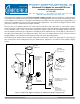
1. Attach the mounting channel to the viscometer by threading the upper mounting screw (HT-19) into the
viscometer pivot cup. Do not overtighten. The end of the mounting channel with the pin must be at the
bottom, as shown in Figure 1.
2. Open Tube Operation (#304 stainless steel)
The water jacket (ULA-49EAY) must be removed when the “open tube” method is used. This allows
measurement in a beaker or other container. The sample chamber must be inserted into the clamping collar
before immersion in sample uid. The top of the sample chamber should be ush with the top edge of the
clamping collar.
The clamping collar connects to the mounting channel as shown in Figure 1. Attach the spindle to the
viscometer by raising the spring-loaded sleeve at the base of the viscometer pivot cup and inserting the
spindle so that the bottom of the coupling is ush with the bottom of the sleeve. Slide the sleeve back down
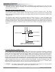
to hold the spindle in place. Slowly lower spindle/chamber assembly into sample uid. Observe and ensure
that the uid level meets the immersion groove located on the outside of the sample chamber as shown in
Figure 2.
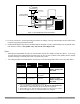
3. Closed Tube Operation with Water Jacket
The UL Adapter may be used with the ULA-49EAY water jacket and a circulating water bath by connecting
the water jacket to the bath inlet and outlet ports (Figure 3). The tube end cap (ULA-34) is snapped over the
bottom end of the sample chamber before the sample is added. Be sure that it is securely seated in the groove.
Fill with 16 mL of sample uid. Insert the clamping collar into the mounting collar as shown in Figure 1.
Insert the sample chamber upwards into the water jacket and clamping collar. When fully inserted, secure the
sample chamber by tightening the clamping knob. Attach the spindle to the viscometer by raising the spring-
loaded sleeve at the base of the viscometer pivot cup and inserting the spindle so that the bottom of th coupling
is ush with the bottom of the sleeve. Slide the spindle into the chamber. Attach the Clamping Collar to the
Mounting Channel, slide upwards, and secure in place by tightening the mounting screw. Conrm that the
uid level in the sample chamber covers the conical portion of the spindle shaft.
CAUTION: The spindle, sample chamber, and cap (if used) should be clean before use. The cap material
is low density polyethylene. Replace when damaged or loose.
CLAMPING COLLAR
CLAMPING KNOB
IMMERSION GROOVE
END CAP GROOVE
Figure 2: Sample Tube Immersion
Chamber Shown is #304 Stainless Steel