TM ® SIMP HOME LIFE BY DESIG N TM DRAPER / BAXTER / TIERNEY DOUBLE DOOR WALL CABINET MODEL # AXCBCDRP-04 1/22
TM ® SIMP HOME LIFE BY DESIG N TM Questions, problems, assembly help, missing parts? No need to return the product, we will gladly help and ship your replacement parts free of charge Please call Customer Service at 1-866-518-0120 ext. 262 Monday to Friday between 9 am –4 pm EST or go to www.simpli-home.
IMPORTANT : Please read this manual carefully before beginning assembly of this product. Keep this manual for future reference. SAFETY INFORMATION Identify all the parts and hardware. Do not discard of the packaging until you have checked that you have all of the parts and hardware required. Hardware package may have spare parts. WARNING: This item contains small parts which can be swallowed by children and pets. Keep children and pets away during assembly.
IMPORTANT : Please read this manual carefully before beginning assembly of this product. Keep this manual for future reference. CARE and MAINTENANCE Perhaps the greatest environmental damage to wood furniture comes from wide swings in relative humidity (RH) in our homes. Wood absorbs and desorbs water as relative humidity rises and falls, and in doing so it swells and shrinks. Making matters worse, it expands and contracts unequally along different grain directions.
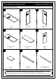
PRE-ASSEMBLY INFORMATION . PART DESCRIPTION A MODEL # AXCBCDRP-04 . . BL BR Fron t van t/A Fron t/A van t vant t/A Fron TOP QTY 1 . LEFT SIDE QTY 1 RIGHT SIDE QTY 1 . . C E D t van t/A Fron vant t/A Fron BOTTOM SHELF QTY 1 . . F . G SHELF QTY 2 DIVIDER QTY 1 MIDDLE SHELF QTY 1 H BACK BAR QTY 1 WALL MOUNT BAR QTY 1 NEED HELP? For help with assembly or if you are missing a part, Please call customer service at 1-866-518-0120 ext.
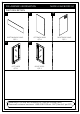
PRE-ASSEMBLY INFORMATION . PART DESCRIPTION I . . IL BOTTOM BACK PANEL QTY 1 . MODEL # AXCBCDRP-04 IR LEFT BACK PANEL QTY 1 RIGHT BACK PANEL QTY 1 . JL JR LEFT DOOR QTY 1 RIGHT DOOR QTY 1 NEED HELP? For help with assembly or if you are missing a part, Please call customer service at 1-866-518-0120 ext.
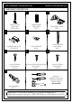
PRE-ASSEMBLY INFORMATION . MODEL # AXCBCDRP-04 HARDWARE DESCRIPTION 1 2 . CAM LOCK PIN CAM LOCK QTY 16 SETS . . 3 WOOD DOWEL Ø8 X 30mm QTY 5 . 4 ADJUSTABLE HINGE QTY 4 . 5 . 7 . 8 PHILLIPS SCREW M4 X 15mm QTY 24 PHILLIPS SCREW M4 X 50mm QTY 7 SHELF SUPPORT QTY 8 MAGNET AND PLATE QTY 2 SETS . 6 PHILLIPS SCREW ROUND HEAD M4 X 15mm QTY 7 9 PHILLIPS SCREW M3 X 15mm QTY 8 .
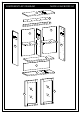
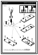
COMPONENTS-KEY DIAGRAM MODEL # AXCBCDRP-04 Fron t / Av A ant H G IL IR Fron Fron t / Av t / Av Fron t / Av ant ant E ant F F BR BL D I C Fron t / Av ant JR JL 8/22
ASSEMBLY MODEL # AXCBCDRP-04 P STEP-1 X 1 Fron t/A van t BL 1 1 Fron t/A BR vant 1 1 1 1 1 C t/ Fron nt Ava A t van t/A Fron 1. Attach Cam Lock Pins 1 into pre-drilled holes on parts A , BL , BR , C . 2. Use Phillips screwdriver to secure Cam Lock Pins. Do not over-tighten.
ASSEMBLY MODEL # AXCBCDRP-04 9 STEP-2 4 t/ Fron nt Ava E 2 9 2 G 2 1.AttachMagnets4usingPhilpsScrews9intopre-driledholesDividerE. 2. Use Phillips screwdriver to secure screws. Do not over-tighten. 3. Insert Dowels 2 into guide holes on each part E , G . 4. Use rubber mallet to tap Dowels 2 into bottom of holes securely. 1/2 length of Dowels should be exposed.
ASSEMBLY MODEL # AXCBCDRP-04 STEP-3 Front / Avant E D 6 6 1. Align Wood Dowel with guide holes and attach Divder E to Middle Shelf D . 2. Use two Phillips Screws 6 to attach Middle Shelf D through guide holes from Middle Shelf D to pre-drilled holes of Divider E . 3. Use Phillips screwdriver to secure Screws. Do not over-tighten.
ASSEMBLY MODEL # AXCBCDRP-04 STEP-4 Front / Avant BL Front / Avant E G D BL Front / Avant 1 Front / Avant E G D 1 1 1. Align Wood Dowels and Cam Lock Pins with guide holes and attach parts D , G to Left Side BL . 2. Insert two Cam Locks 1 into guide holes on Middle Shelf D . 3. Use Phillips screwdriver to secure Cam Locks.
ASSEMBLY MODEL # AXCBCDRP-04 STEP-5 Front / Avant G Front / Avant BR Front / Avant E D BL G Front / Avant 1 1 Front / Avant BR Front / Avant E BL D 1 1. Repeat Step-4 for the Right Side BR .
ASSEMBLY MODEL # AXCBCDRP-04 STEP-6 Front / Avant E Front / Avant Front / Avant BL D C Front / Avant BR 1. Align Cam Lock Pins with guide holes and attach part C to Sides BL , BR . t / Avan Front t / Avan BL ant / Av Front BL 1 C Front / Avant 1 BR Front / Avant BR Front / Avant Front / Avant Front C 2. Insert two Cam Locks 1 into guide holes on each Side BL , BR . 3. Use Phillips screwdriver to secure Cam Locks.
ASSEMBLY MODEL # AXCBCDRP-04 STEP-7 Warning Label G IR Fron t/A vant IL BL BR I C 1.SlideBackPanelsI,IL,IRfirmlyintoslotsonSidesBL,BRandBottomShelfC.
ASSEMBLY MODEL # AXCBCDRP-04 STEP-8 A t van t/A Fron t van t/A Fron t van t/A Fron BL E t van t/A Fron BR C vant t/A Fron 1. Align Cam Lock Pins with guide holes and attach part A to parts BL , BR , E . 1 A Front / Avant Front / Avant BL E 1 Front / Avant BR C 2. Insert Cam Locks 1 into guide holes on each part BL , BR , E . 3. Use Phillips screwdriver to secure Cam Locks.
ASSEMBLY MODEL # AXCBCDRP-04 STEP-9 A t Fron ant / Av 8 IL t Fron ant / Av IR I 1.UsePhilpsScrewsRoundHead8toattachBackPanelsI,IL,IRthroughguideholes. 2.UsePhilpsscrewdrivertosecureScrews.Donotover-tighten. STEP-10 A t van t/A Fron ant / Av t Fron t van t/A Fron F t Fron ant / Av F 5 1.UsefourShelfSupports5foreachCabinetShelfFindesiredlocation.
ASSEMBLY MODEL # AXCBCDRP-04 STEP-11 9 7 JR 3 4 JL 1. Attach Adjustable Hinges 3 to Doors JL , JR using Phillips Screws 7 into pre-drilled holes on Doors JL , JR . 2.AttachMagnetPlates4totopcornerofDoors JL , JRusingPhilpsScrews9into pre-driledholesonDoors JL , JR. STEP-12 A BR JR 3 BL 7 JL 1. Attach Adjustable Hinges 3 on Doors JL , JR to Sides BL , BR using Phillips Screws 7 into pre-drilled holes on parts BL , BR . 2. Use Phillips screwdriver to snugly tighten screws.
ASSEMBLY MODEL # AXCBCDRP-04 STEP-13 IMPORTANT NOTE: 7 II I Tighten the Screw marked II to fasten hinge. The door may need to be adjusted so that all the spaces between the door and the unit sides are equal. To adjust, follow instructions: 1. Side adjustment 4 mm To move the door towards the side panel, loosen screw I and tighten screw II . To move the door away from the side panel, loosen screw II and tighten screw I . 2.
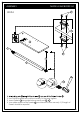
ASSEMBLY MODEL # AXCBCDRP-04 STEP-14 - Positioning H e d b c a 10 1. Determine the location for the unit on the wall. The Top A should be approximately 1 ¼” above the top of the Wall Mount Bar H when mounted. 2. Place the Wall Mount Bar H at the predetermined height. Use a level to ensure that it is straight. The flat side of Wall Mount Bar H should face outward away from the wall. Hole (c) should align with your studs. Carefully mark the position of each hole using the tip of the Phillips Screw 6 .
ASSEMBLY MODEL # AXCBCDRP-04 STEP-16 H H H 1. Align the top of the Wall Mount Bar H with the bottom of the angled bracket on the back of the Cabinet. 2. Gently slide the Cabinet down on to the Wall Mount Bar H .
TM ® SIMP HOME LIFE BY DESIG N TM WARRANTY Thank you for purchasing a Simpli Home – Wyndenhall – Brooklyn + Max product. These products have been made to demanding, high-quality standards and are guaranteed for domestic use against manufacturing faults for a period of 12 months from the date of purchase. This warranty does not affect your statutory rights. In case of any malfunction of your product (failure, missing parts, etc.) please contact us at our toll free service line at 1-866-518-0120 ext.